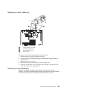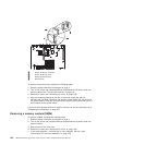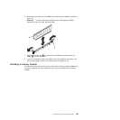
v The expansion slots in the PCI riser cards accommodate the various form factors
of the non-hot-plug adapters as follows:
– Expansion slot 1: Full-height, full-length
– Expansion slot 2: Low-profile with standard bracket
– Expansion slot 3: Full-height, full-length
– Expansion slot 4: Full-height, half-length
If you install a different supported riser-card assembly, the supported adapter
types might be different. For a list of supported riser-card assemblies, see
http://www.lenovo.com/thinkserver.
v The system scans devices in the following order, if you have not changed the
default boot precedence:
– Video unified extensible firmware interface (UEFI) (fixed)
– System board Ethernet 1 PXE (fixed)
– System board Ethernet 2 PXE (fixed)
– System board SAS (or RAID)
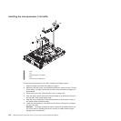
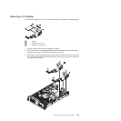
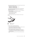
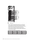
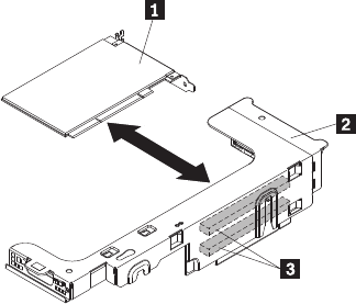
The following illustration shows the adapter connectors on the PCI riser-card
assembly.
1 Adapter
2 PCI riser-card assembly
3 Adapter connectors
To install a PCI adapter, complete the following steps:
1. Read the safety information that begins on page 3.
2. Turn off the server and peripheral devices and disconnect all power cords and
external cables (see “Turning off the server” on page 53).
3. Remove the cover (see “Removing the cover” on page 159).
4. Determine which expansion slot you will use for the adapter.
5. If you are installing an adapter in PCI expansion slot 1 or 2, remove PCI
riser-card assembly 1; if you are installing an adapter in PCI expansion slot 3
or 4, remove PCI riser-card assembly 2. See “Removing a PCI riser-card
assembly” on page 167.
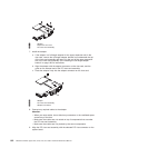
6. Slide the expansion-slot cover out of the PCI riser-card assembly expansion
slot.
Chapter 6. Removing and installing FRUs 181


