


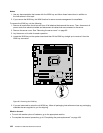
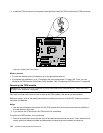
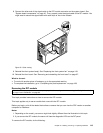
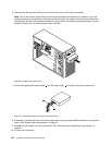
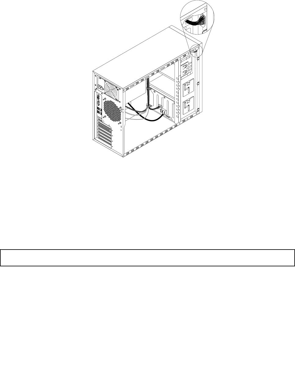
8. Connect the other end of the signal cable to the DIT module connector on the system board. See
“System board components” on page 42. Then, properly route the signal cable of the DIT module. You
might need to secure the signal cable with cable clips or ties in the chassis.
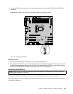
Figure52. Cable routing
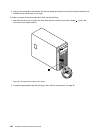
9. Reinstall the front system fan(s). See “Replacing the front system fan” on page 149.
10. Reinstall the front bezel. See “Removing and reinstalling the front bezel” on page 87.
What to do next:
• To work with another piece of hardware, go to the appropriate section.
• To complete the installation, go to “Completing the parts replacement” on page 168
.
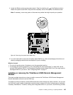
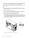
Removing the DIT module
Attention: Do not open your server or attempt any repair before reading and understanding the “Safety information”
on page iii
and “Guidelines” on page 83.
This topic provides instructions on how to remove the DIT module.
This topic applies only to server models that come with the DIT module.
Before you begin, print all the related instructions or ensure that you can view the PDF version on another
computer for reference.
Notes:
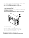
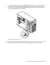
1. Depending on the model, your server might look slightly different from the illustration in this topic.
2. If you remove the DIT module, the server will lose the diagnostic LEDs on the DIT panel.
To remove the DIT module, do the following:
Chapter 6. Installing, removing, or replacing hardware 113