


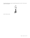
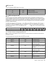

2 BMC status LED
This LED indicates the BMC status of your server.
BMC status LED Color
Description
On Green The BMC is not ready.
Off
None
The BMC has no power or fails.
Blinking
Green The BMC is working.
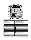
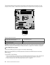
3 - 10 POST code diagnostic LEDs
During the system boot process, the BIOS executes several platform conguration processes, each of
which is assigned a specic hex POST code number. When each conguration routine is started, the BIOS
displays the POST code number through the POST code diagnostic LEDs on the system board. To assist in
troubleshooting a system hang during the POST process, the diagnostic LEDs can be used to identify the
last POST process executed.
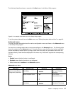
The POST code diagnostic LED #0 (callout 4 ) is the LSB and the POST code diagnostic LED #7 (callout 9 )
is the MSB. If a POST code diagnostic LED is lit, it indicates 1 in the binary numeral system; otherwise, it
indicates 0. For example, if POST code diagnostic LEDs
5 , 6 , 9 , and 10 are lit, you can read the number
as the following:
POST code diagnostic LED
9 7 5 3 10 8 6 4
Binary symbol 1 0 1 0 1 0 1 0
The “10101010” indicates a corresponding POST code.
Note: The POST code diagnostic LEDs and POST error code information are intended for trained service
personnel of Lenovo.
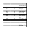
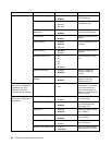
The following table lists information about the POST error codes.
POST code diagnostic LEDs POST error code
Description
00001110 0x0E
Microcode not found.
00001111 0x0F Microcode not loaded.
01010000 0x50 Memory initialization error. The
memory type is invalid or the memory
speed is incompatible.
01010001 0x51
Memory initialization error. The Serial
Presence Detect (SPD) data reading
has failed.
01010010 0x52 Memory initialization error. The
memory size is invalid or the memory
modules do not match.
01010011 0x53 Memory initialization error. No usable
memory detected.
01010100 0x54
Unspecied memory initialization
error.
01010101 0x55 Memory not installed.
01010110 0x56 Invalid microprocessor type or speed.
Chapter 3. Product overview 51