Operation
30
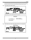
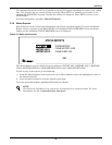
New Target and Ramp settings are temporary settings for diagnostic testing or special situations.
Each time the UPS is placed online, the settings return to the default values. Custom T and R entries
are only allowed when rotary switch is in Bypass position.
The Operator normally does not have to change Target and Ramp settings. Therefore, he should
select SKIP and proceed to the next step which is to turn on the Rectifier and Inverter.
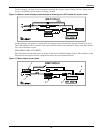
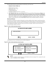
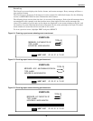
Operator is issued the prompt on the Mimic Display, “Turn on Rect.” Pressing OK will turn on the rec-
tifier which will take up to one minute. If the rectifier does not turn on within two minutes, the UPS
will automatically make a second attempt.
Next, Operator is issued the prompt, “Turn on Inv.” Pressing OK turns on the inverter, taking up to
one minute. If it does not turn on within two minutes, the UPS will make a second attempt.
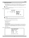
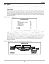
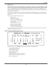
Next, Operator is prompted to “Close Batt CB.” The battery circuit breaker does not have to be closed
to bring the unit online. This step can be skipped in both NORMAL and BYPASS positions. The
CLOSE BATT CB screen will offer a choice of OK or SKIP. If you wish to move ahead without bring-
ing the battery online, select SKIP.
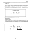
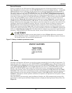
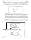
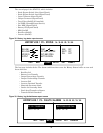
Last, the Operator will see the MANUAL TRANSFER/RETRANSFER screen. To move the unit from
BYPASS to UPS operation use the arrow keys to select RETRANSFER TO UPS and push the
SELECT button.
At any time during the above sequences, the Operator can choose to abort the procedure. The load will
remain on bypass while the rectifier and inverter are powered down. In addition, any internal failure
will automatically inhibit startup.
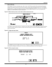
From here on the Operator may monitor faults/alarms data and other information by navigating to
primary screens from the Main Menu screen, or by navigating to secondary screens from any of the
primary screens.
SIB External Maintenance Bypass
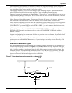
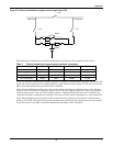
An External Maintenance Bypass Switch can be added by Liebert or supplied by the Customer. The
Liebert supplied option is outlined in Figure 27 and Figure 28 for the single input and dual input
options, respectively. The rotary switch has three independent power contacts on a common shaft. A
set of auxiliary contacts is incorporated into the shaft to determine the power switch position. The
auxiliary contacts, if provided will be connected to pins 9-10 of TB70 of the UPS module. The UPS
module shipped from the factory will have pins 9-10 jumpered so that the UPS internal logic will
ignore the External Maintenance Bypass switch conditions.
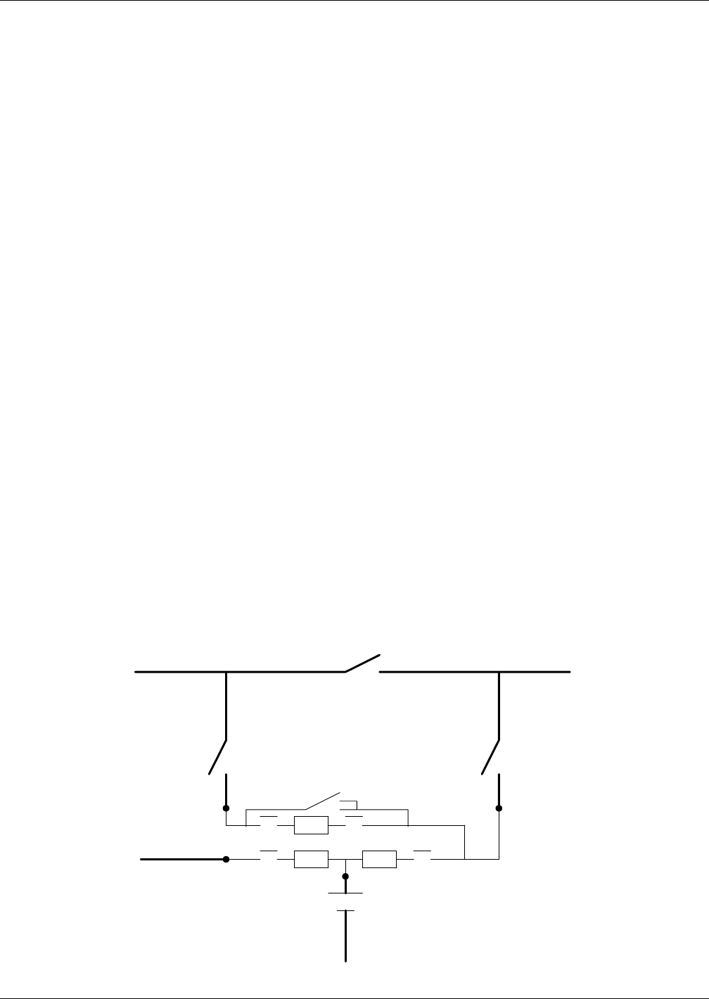
Figure 27 External maintenance bypass switch, dual-input UPS
S1-A
S1-B
S1-C
SBS
Rect INV
Battery
Rectifier Input
Bypass Input
Critical Load
IMBS


