Operation
89
3.5.1 RS-232 Port: Local Reporting Terminal
The Npower transmits UPS system status and history information to a remote terminal through an
RS-232 Port in ASCII Format. This feature is called the Service Terminal. The service terminal inter-
face is intended to be accessed via PC terminal emulation software like Procomm Plus, Microsoft Win-
dows Terminal or Hyperterminal, or directly through a standard ASCII terminal.
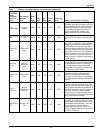
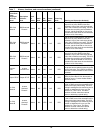
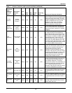
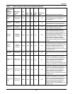
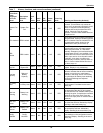
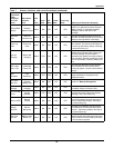
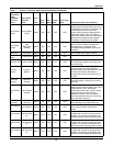
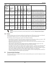
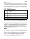
A summary of Npower service terminal commands is provided in Table 8 below. Two types of com-
mands are identified: operational (OPS) and diagnostic (DIAG). Operational commands deal prima-
rily with machine operations: metering, alarm events and transient analysis. This information is also
available through the front panel Operator interface. Diagnostic commands are intended to allow
manipulation of the internal machine operating parameters. Access to these commands is limited
through password protection.
In addition to the local RS-232 Port, Npower will interface with an External modem which uses the
same ASCII command set. Likewise the SiteScan port can support SiteScan communications. What-
ever communication options are installed in the Npower UPS can all be used simultaneously.
3.5.2 Worldwide Reporting
The Npower has a standard Interface Terminal Block to connect to an optional external modem. An
internal optional modem can also be installed, although the external modem cannot be utilized if the
system is configured with an internal modem. The internal modem is compatible with standard ana-
log telephone lines and most standard telephone equipment. The internal or external modems allow
you to configure the UPS to:
1. Make outgoing calls to a computer in an attempt to notify of a pressing alarm condition.
2. Accept incoming calls so a remote computer can connect to the UPS and serve as a monitoring
station.
3. Make outgoing calls to a pager.
Auto-Dial
The Npower will automatically dial a pre-programmed (customer-selected) phone number when spec-
ified alarm conditions occur. The auto-dial phone number, an alternate number, and the modem baud
rate are programmed by using the System Configuration screen. (See Options Manual for program-
ming instructions.) The alarm messages that initiate an auto-dial call are identified in Table 7.
When the auto-dial function is initiated, automatic dial attempts three times to dial the first phone
number at 45 second intervals. If unanswered, the system rolls over to the second number and
repeats the sequence. After three tries on each line, the auto dial function is discontinued, at which
point the pager module (See Dial Out Pager on page 90) gains access to the modem.
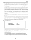
Once a connection is made, the system transmits the information on the Present Status Report
screen, then hangs up. The Present Status Report in ASCII Format includes the UPS system identifi-
cation number, date, time, alarm messages and metered parameter indications.
Table 8 Service terminal command summary
Command Type Description
? OPS Reports a command listing (same as HELP?) OR provides help with specific
commands.
AA? OPS Reports active alarms.
AF? OPS Reports active faults.
DATE? OPS Reports the current date.
EL? OPS Reports entire event log, most recent on top.
HELP? OPS Reports a command listing (same as?) OR provides help with specific commands.
HL? OPS Reports the entire requested history log (comma delimited) if frozen, from oldest frame
to newest.
SPT? OPS Reports setpoints for group number.
SR? OPS Reports active status reports.
TIME? OPS Reports the current time in military format.
UPMDR? OPS Reports metering data using real values.


