


Host-Based Modem Data Addendum
AT Command Set June 15,
1998
24 Version 1.0 Lucent Technologies Inc.
Test and Debug AT Commands
The following commands are to be used for testing and debugging only and are not meant for general use.
&&C Write to / Read from DSP Register
AT&&C<loc>,<val> writes the value <val> to DSP register at location <loc>.
AT&&C<loc> reads from location <loc>.
&&L Line-to-Line Loopback
This command provides a loopback for line-to-line.
&&R Write to/Read from DSP RAM Location
AT&&R<loc>,<val> writes the value <val> to DSP RAM location <loc>.
AT&&R<loc> reads from location <loc>.
&&S Speaker Codec Loopback
This command provides a loopback from the microphone to the speaker.
%T94 Test External RAM
This command “AT%T94” is used for testing the external RAM. If the external RAM is good, this command returns
“PASS”. If the external ram is not good, this command returns “FAIL”.
Example :
AT%T94
PASS - external ram is good
%T125, %T124 Test DSP 56K Version in External Ram
The command “AT%T125” is used for testing the DSP 56K code version and checksum running in external ram.
After issuing “AT%T125” the user may then issue “ATI4” to get DSP Version or “ATI1” to get the DSP checksum.
(The command “AT%T125” is not valid for ramless version of the DSP 56K code.)
The command “AT%124” is for internal ram version.
#UD Unimodem Diagnostics
The reference for the #UD command is Microsoft’s Draft Reference Specification rev.0.85. The Lucent
Technologies modem implements a subset of the parameters in that document.
#UD is an action command. It does not take parameters. It shall be the last command in the command line.
The modem logs aspects of its operation for each call, and saves these results (in volatile memory) until cleared
by one of the following events:
1.
Power off (or D1 or D3 state entered)
2.
Hard reset (e.g. negate DTR with &D3 set, reset button)
3.
Soft reset = ATZ or AT&F
4.
ATD command issued
5.
ATA command issued
6.
Automatic answer (e.g. set register S0>0 and ring detected)
These results are NOT cleared by changing DTR, V.24 circuit 108.2, if &D0, &D1 or &D2.
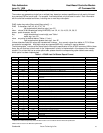
In response to this command, the modem reports one or more lines of information text as defined below.
Information text format is defined in ITU V.25ter: each line is preceded by a <CR><LF> pair, and terminated by
<CR><LF>. (Note: as per V.25ter, CR and LF characters may be changed by writing new values to the contents
of registers S2 and S3 respectively.)