


Host-Based Controller Modem Data Addendum
AT Command Set June 15, 1998
AT Commands Reference S-Registers (continued)
Lucent Technologies Inc. Version 1.0
32
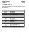
S21 V.24/General Bit Mapped Options Status
Indicates the status of command options. Only bits 3, 4 and 5 are used, read-only.
Bits 3-4 DTR behavior (&Dn)
0 = &D0 selected
1 = &D1 selected
2 = &D2 selected (Default)
3 = &D3 selected
Bit 5 DCD behavior (&Cn)
0 = &C0 selected
1 = &C1 selected (Default)
Default: 48 (00110000b)
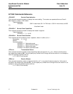
S22 Results Bit Mapped Options Status
Indicates the status of command options. Only bits 4, 5 and 6 are used, read only.
Bits 4-6 result codes (Xn)
0 = X0 selected
4 = X1 selected
5 = X2 selected
6 = X3 selected
7 = X4 selected (Default)
Bit 7 Pulse dial make/break ratio (&Pn)
0 = 33/67 make/break ratio (&P1, &P2) (Default)
1 = 39/61 make/break ratio (&P0)
Default: 112 (01110000b)
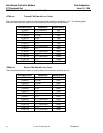
S24 Timer to Control Sleep Mode
This command displays the number of seconds of inactivity (no characters sent from the DTE, no RING) in the
off-line command state before the modem places itself into standby mode. A value of zero prevents standby
mode. S24 is an alias for S89.
Note: If a number between 1 and 4 is entered for this register, it will set the value to 5, and the inactivity before
standby will be 5 seconds. This is done for compatibility with previous products which allowed time-outs
down to 1 s.
Range: 0, 5—65
Default: 10
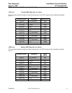
S28 V.34 Modulation Enable/Disable
This register enables/disables V.34 modulation.
0 = disabled, 1 = enabled
Range: 0 —1
Default: 1