


Data Addendum Host-Based Controller Modem
June 15, 1998 AT Command Set
AT Commands for Homologation Testing and Debugging (continued)
Version 1.0 Lucent Technologies Inc.
67
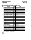
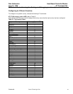
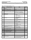
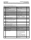
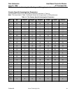
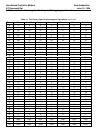
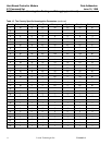
Table 13. The Homologation Parameters (continued)
Par #
Parameter Description Range
Reference
31 TAD receive gain 0—255 —
32 Half/full wave ring detection 0 = halfwave, 1 = fullwave —
33 Number of failed attempts allowed in first stage
delayed dialing
0—255 ATD
34 Number of all failed attempts ( to any number)
allowed before any further dial attempts are blocked
0—255
255 = not applicable
ATD
35 Erroneous call increment count 0—255 ATD
36 Dial tone validation time in multiples of 100 ms 0—255 ATD
37 Busy tone detection during dial tone detection flag 0 = not required, 1 = required ATD
38 DTMF high and low tone level difference in dB 0—255 —
39 Local phone detection in speakerphone 0 = enabled; 1 = disabled —
3a Pulse dialing flag 0 = enabled; 1 = disabled ATD
3b Dial tone/call progress filter index 0 = 340—560 Hz 1 = 310—485 Hz
2 = 363—502 Hz 3 = 276—504 Hz
4 = 415—460 Hz 5 = 310—640 Hz
—
3c Dial tone detection threshold in dB 0—255 —
3d ABCD dialing permitted flag 0 = permitted, 1 = not permitted ATD
3e Comma pause duration limit in seconds. (If there are
multiple commas between digits, the total pause
duration is limited to the duration set by this
parameter).
0—255 ATD
3f TAD transmit level in dB 0—255 —
40 Data/FAX carrier receive threshold in dB. There is a 6
dB offset in DSP. This parameter value should set to:
(required threshold [6 dB] DAA gain)
0—255 —
41 No dialtone time-out duration while detecting dialtone
with W dial modifier, in seconds
0—255 ATD
42 FAX/Data answer tone detection threshold in dB 0—255 —
43 Dialtone level (absolute value) 0—255 —
44 FAX receive threshold in dB 0—255 —
45 Pulse and tone dial in same dial string permitted flag 0 = permitted, 1 = not permitted ATD
46 Ringer impedance relay flag 0 = off, 1 = on
47 DC loop V/I characteristics relay flag 0 = off, 1 = on
48 DC loop limiting relay flag 0 = off, 1 = on
49 Real/complex impedance 0x0X = real, Tx & Rx gains set by mercury
internal components. X = Don’t care
0x10 = real, Tx gain set by mercury
internal components & Rx gain set by
external components.
0x12 = complex, Tx gain set by mercury
internal components & Rx gain set by
external components. Mercury internal
switch used to select complex impedance.
4a Mercury register CIOCA MSB value—receive gain This parameter is relevant only when a Mercury
line codec is used.
—