


Comet installation and user manual: E-6761200XT/FC
2.2
Merlin Gerin by MGE UPS SYSTEMS
special precautions
installation (cont')
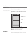
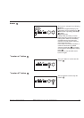
Note:
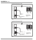
For Comet series 31 15/20kVA and Comet series 33 units, a clearance "e" of
5mm is required to the left of the optional cubicles for door opening.
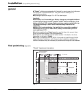
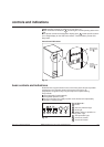
■ ensure that clearance L1 to the left of Comet is greater than L for access to the
battery cells and L2 greater than 100mm (for ventilation);
■ ensure that clearance P1 in front of Comet is greater than P for servicing via
the front;
■ connection cables must be of th flexible type and sufficiently long to enable
forward movement of Comet without disconnection (allow an extra 1.5 meters);
■ additional cubicles (extended battery, auxiliaries, etc.) must be placed to the
right of Comet. If the above installation conditions are not respected,
maintenance and servicing of the unit may require system shutdown.
■ load cables must be run separately from all other cables (power supply or
computer system interconnection cables). They should not pass near
interference-emitting equipment or sensitive loads;
■ if Comet is installed with the "Teleservice" option, a telephone connector and
power supply must be provided for the modem used with it.
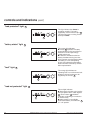
Connection cables should enter at the bottom:
■ in the back for Comet series 11 and series 31 5/7.5/10kVA;
■ in front for Comet series 31 15/20 kVA and series 33 10/15/20/30kVA.
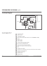
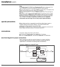
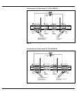
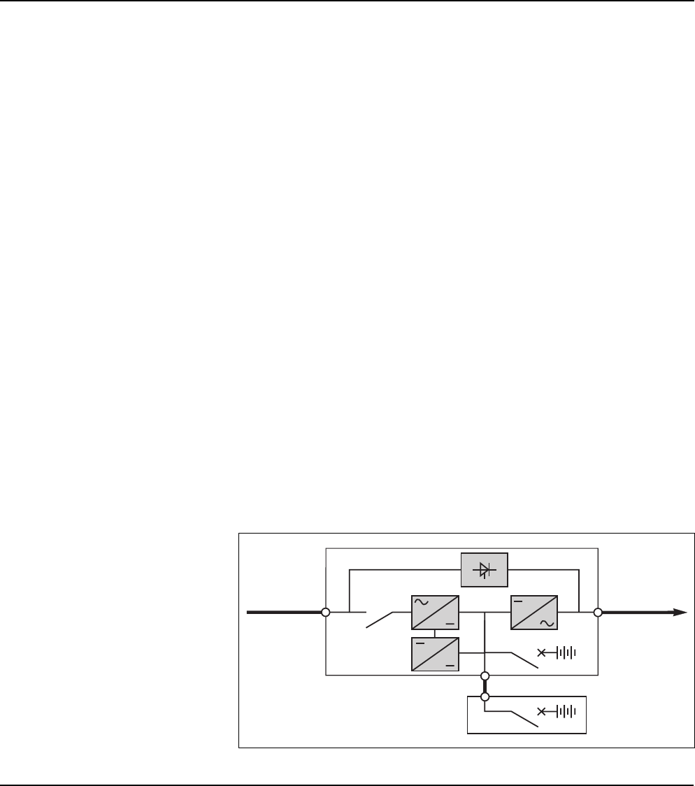
Figure 9 presents a single-line electrical diagram for a typical installation.
The power cables requiring connection are shown as bold lines (see the
"appendices" for information on selecting cable cross-sections).
Fig. 9
connections
electrical diagram for power connections
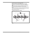
Connection diagram for a single AC input
load
AC input
extended battery
cubicles (optional)
XR3
XR3
XR2XR1
Comet