


10.4
Comet installation and user manual: E-6761200XT/FA Merlin Gerin by MGE UPS SYSTEMS
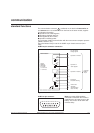
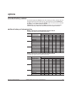
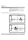
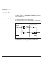
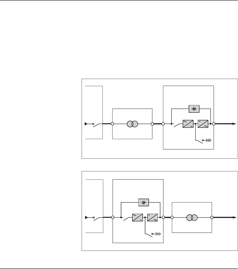
full galvanic isolation transformer (standard Comet equipment)
power connection diagrams
This option is required to achieve a downstream neutral system different from the
upstream neutral system. The transformer, installed in a cubicle of the same
design as the Comet cubicle, must be positioned:
■ between the low voltage switchboard and the input power switch for Comet
series 11 and series 33 (see figure 26);
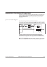
■ between the Comet load output terminals and the load for Comet series 31
(see figure 27).
The cables requiring connection are indicated as bold lines.
For information on cable cross-sections, see the "appendices": "selection of cable
cross-sections" (the connection cable between Comet and the option is supplied).
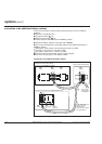
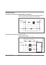
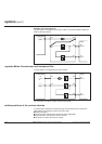
Fig. 26
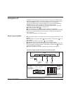
Fig. 27
XR5XR4
transformer
load
XR1
Comet series 31
CB1
TR2
XR2
LV
switchboard
load
XR2
XR1
Comet series 11/33
XR5XR4
transformer
LV
switchboard
TR2
CB1
options (cont')