


Page 27
feet down the cable. The sampling of the voltage is delayed long enough to allow the incident step
to propagate past near end patch cables, cross connects block, etc. that could disrupt the
impedance measurement. The length of the cable must be long enough to produce a round trip
delay, which is longer than the sample time delay. For short cables, the impedance function
measures the termination value.
Note: To measure Impedance correctly, the cable length must be 40 feet or greater. If the cable is
not at least 40 feet long, the Impedance test result will be OVR (Over range) or UND (Under
range).
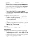
Customizing Impedance Limits
To display the IMPEDANCE LIMITS screen, press the Extended Functions key, then select
Setup Autotest, then highlight the Autotest to edit, then press Edit (F2), then select Limits, then
select Impedance.
This screen lets you change the minimum and maximum Impedance limits. Press the
Ñ or
Ò arrow key to select the minimum or maximum Impedance limit. The selected limit will be
enclosed in a box.
If your Scanner has an alphanumeric overlay on the keypad, use the keypad to enter the limits. If
your Scanner does not have an alphanumeric overlay, press Edit (F2) to display the edit screen.
After editing, press Save (F1) to store the new Impedance limits and exit or press the ESCAPE
key to exit without saving.
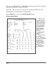
Impedance Test Results
To display the Impedance screen, press View (F1) from the AUTOTEST RESULTS screen, then
press the
Ò key until the IMPEDANCE screen is displayed.
At the upper left of the screen, the pair combination is shown. The Impedance, in ohms (
Ω), is
shown to the right of the pair. The PASS/FAIL bar across the screen compares the measured
Impedance value to the Impedance limit value. Below the PASS/FAIL bar, the Impedance limit
value is displayed. The Autotest name is displayed after Spec: at the lower left of the screen.
Press Table (F1) to display the Impedance test results for all pairs or press Pair (F3) to toggle
through the Impedance results for each pair.
Press the
Ï or Ð arrow key to display the previous or next test results screen.
Press the ESCAPE key to return to the AUTOTEST RESULTS screen.
Note: For diagnostic purposes, you can run Impedance continuously by pressing the Measure
Cable Performance key and selecting Impedance.
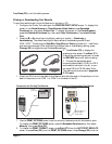
Loop Resistance
Loop Resistance is the combined resistance of two conductors in a twisted pair cable, or the coaxial
shield and center conductor in coaxial cable. In twisted pair cable, Loop Resistance is measured by
using the Injector to short the far end of the pair being tested. In coaxial cable, a shorting plug is
required to measure Loop Resistance. The Loop Resistance range is 0 to 10,000 ohms.