


Resistance is said to fail if measured values on pairs used by the selected network type are greater
than the resistance for a maximum length loop (100 meters for most networks).
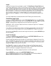
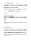
Customizing Loop Resistance Limits
To display the LOOP RESISTANCE LIMITS screen, press the Extended Functions key, then
select Setup Autotest, then highlight the Autotest to edit, then press Edit (F2), then select
Limits, then select Loop Resistance. This screen lets you change the maximum Loop Resistance
limit.
If your Scanner has an alphanumeric overlay on the keypad, use the keypad to enter the limit. If
your Scanner does not have an alphanumeric overlay, press Edit (F2) to display the edit screen.
After editing, press Save (F1) to store the new maximum Loop Resistance limit and exit or press
the ESCAPE key to exit without saving.
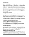
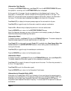
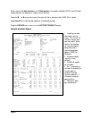
Loop Resistance Test Results
To display the LOOP RESISTANCE screen, press View (F1) from the AUTOTEST RESULTS
screen, then press the Ä key until the LOOP RESISTANCE screen is displayed.
At the upper left of the screen, the pair corresponding to the test result is shown. The Loop
Resistance, in ohms (Ω), is shown to the right of the pair. The PASS/FAIL bar across the screen
compares the measured Loop Resistance value to the Loop Resistance limit value. Below the
PASS/FAIL bar, the Loop Resistance limit value is displayed. The Autotest name is displayed after
Spec: at the lower left of the screen.
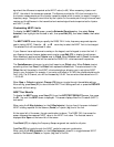
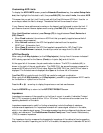
Press Table (F1) to display the Loop Resistance test results for all pairs or press Pair (F3) to toggle
through the Loop Resistance results for each pair.
Press the
Ï or Ð arrow key to display the previous or next test results screen.
Press the ESCAPE key to return to the AUTOTEST RESULTS screen.
Note: For diagnostic purposes, you can run Loop Resistance continuously by pressing the
Measure Cable Performance key and selecting Loop Resistance.
Capacitance
Capacitance is the amount of electric field energy that can be stored between two conductors at a
given voltage. For twisted pair cable, Capacitance is measured between conductors in a pair. For
coaxial cable, Capacitance is measured between the conductor and the shield.
The Capacitance measurement is made by measuring the effective charging and discharging time
constant that is formed by the capacitance of the cable. This is done at low frequency to eliminate
any transmission line effects of the cable under test.
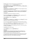
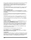
Customizing Capacitance Limits
To display this screen, press the Extended Functions key, then select Setup Autotest, then
highlight the Autotest to edit, then press Edit (F2), then select Limits, then select Capacitance.
Press the
Ñ or Ò arrow key to select the minimum or maximum Capacitance limit. The
selected limit will be enclosed in a box.