


USER’S GUIDE
050396 107/173
108
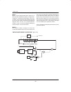
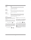
Mode 1
Mode 1 for both programmable timers operates in an
identical fashion described for Mode 0, except Mode 1
configures a 16–bit timer/counter register. In this case,
for Timer 0, TH0 contains the most significant eight bits
of the count value while TL0 holds the least significant
eight bits. Timer 1 uses TH1, TL1 in an identical fashion
in Mode 1. Figure 13–3 is also a diagram depicting op-
eration in Mode 1 for the timer/counters.
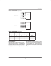
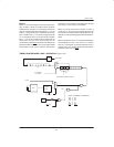
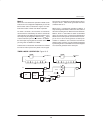
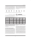
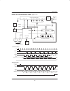
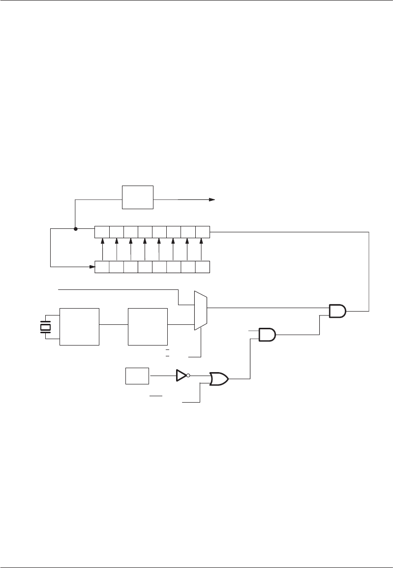
Mode 2
The selection of Mode 2 configures an 8–bit timer/
counter with automatic reload of a value preset by soft-
ware. Figure 13–4 illustrates a functional block diagram
of this operational mode. When Timer 0 is used in
Mode 2, TL0 is incremented as each count is received.
When the value of 0FFH (all 1’s) is reached, TF0 will be
set on the next count and the reload value held in TH0
will be transferred into TL0. TH0 remains unchanged
until it is modified by the application software.
Timer 1 operates in an identical fashion when it is set for
operation in Mode 2.
TIMER/COUNTER MODE 2 OPERATION Figure 13–4
70
MUX
OSC.
DIVIDE
BY 12
1 IF C/T = 1
0 IF C/T
= 0
GATE
INT0
PIN
TR0
TF0
TL0
TH0
T0
INTERRUPT
RELOAD
1
0