


USER’S GUIDE
050396 85/173
86
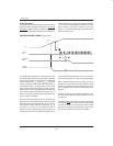
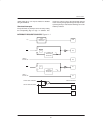
APPLICATION: RESET ROUTINE EXAMPLE
Like the 8051, Dallas Semiconductor Microcontrollers
will begin execution at address 0000h. This is the Reset
Vector, followed by other vector locations used for inter-
rupts. These are discussed in the section covering inter-
rupt operation. Since there are only three memory loca-
tions dedicated to the Reset Vector, the user will
typically insert a jump statement to a more convenient
memory address. This will be the reset routine. It can lie
any where in the 64K bytes of program memory
addressed by the device. A common choice is location
0030h. Thus at location 0000h, the user would use the
instruction SJMP 30h. This instruction requires two
bytes, so it easily fits in the available space. At the loca-
tion of the reset routine, the user places instructions that
initialize the microprocessor and any external hardware
specific to the application. This note describes the
operations that are typically done and shows some
example code.
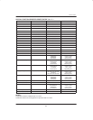
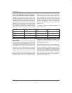
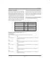
The following functions are typically initialized in a
user’s reset routine:
MEMORY
INTERRUPTS TIMERS/SERIAL PROTECTION
Partition Power–fail Timer setup Watchdog Timer
Current Memory Map External Timer for baud–rates POR
Data Pointer Serial Port Serial Port
Timer
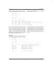
Memory Map
The most critical and most overlooked initialization is
that of the memory map. Several of these functions are
nonvolatile and are not cleared during a reset. Those
that are cleared could leave the microprocessor in an
undesirable state. Therefore, the user should either
verify the correctness of the memory map or simply set it
properly following each reset. An example of how the
memory map could be incorrect on reset is as follows.
The user typically sets the Partition, Range, etc., during
Bootstrap Loading. In the course of operating however,
the user may temporarily move the Partition to alter a
lookup table. If while the Partition is moved, a reset
should occur, the Partition will remain in the temporary
position unless corrected.
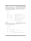
In developing the reset routine, the user should carefully
note the reset state of each critical bit. For example,
when using the ECE2 on a DS5000FP, note that it is not
altered on reset. On a DS5001FP, the PES bit is cleared
on a reset. Thus a DS5000T that is accessing the Real–
time Clock when a reset occurs will still be pointing the
CE2 space after reset. The DS2251T user that is
accessing the RTC when a reset occurs will start in the
normal memory configuration.