


USER’S GUIDE
050396 60/173
61
Write Access: Cannot be written.
PCON.3: EPFW
“Enable Power Fail
Interrupt”: Used to enable or disable the Power Fail Interrupt. When EPFW is set to a 1,
it will be enabled; it will be disabled when EPFW is cleared to a 0.
Initialization: Cleared to a 0 on any type of reset.
Read Access: Can be read normally anytime.
Write Access: Can be written normally anytime.
PCON.1: STOP
“Stop”: Used to invoke the Stop mode. When set to a 1, program execution will ter-
minate immediately and Stop mode operation will commence. Cleared to a 0
when program execution resumes following a hardware reset.
Initialization: Clear to a 0 on any type of reset.
Read Access: Can be read anytime.
Write Access: Can be written only by using the Timed Access register.
PCON.0: IDL
“Idle”: Used to invoke to Idle mode. When set at a 1, program execution will be
halted and will resume when the Idle bit is cleared to 0 following an interrupt
or a hardware reset.
Initialization: Cleared to 0 on any type of reset or interrupt.
Read Access: Can be read normally anytime.
Write Access: Can be written normally anytime.
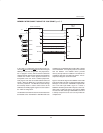
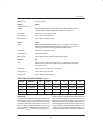
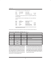
PIN STATES IN IDLE/STOP MODES Table 7–1
MODE
PROGRAM
MEMORY
ALE PSEN P0 P1 P2 P3
Idle Byte–wide 1 1 Port Data Port Data Port Data Port Data
Idle Expanded 1 1 Hi–Z Port Data Address Port Data
Stop Byte–wide 1 0 Port Data Port Data Port Data Port Data
Stop Expanded 1 0 Hi–Z Port Data Port Data Port Data
Stop Mode
The Stop mode is initiated by setting the STOP bit in the
PCON register (PCON.1). The operation of the oscilla-
tor is halted in the Stop mode so that no internal clocking
signals are produced for either the CPU or the I/O cir-
cuitry. An External Reset via the RST pin is the only
means of exiting this mode without powering down (V
CC
taken below V
CCmin
) and then back up to produce a
Power On Reset. The STOP bit may only be set by using
the Timed Access software procedure described in Sec-
tion 8. Since the oscillator is disabled in this mode, the
Watchdog Timer will cease operation. When the exter-
nal reset signal is issued to terminate the Stop mode, a
21,504 clock delay will be generated to allow the clock
oscillator to start up and its frequency to stabilize as is
done for a Power On Reset as described in Section 10.