


XTAL2
XTAL1
GND
NC
EXT. OSC.
SIGNAL
USER’S GUIDE
050396 123/173
124
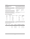
SECTION 15: CPU TIMING
OSCILLATOR
The Secure Microcontroller provides an on–chip oscilla-
tor circuit which may be driven either by using an exter-
nal crystal as a time base or from a TTL–compatible
clock signal. The oscillator circuitry provides the internal
clocking signals to the on–chip CPU and I/O circuitry.
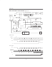
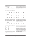
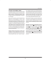
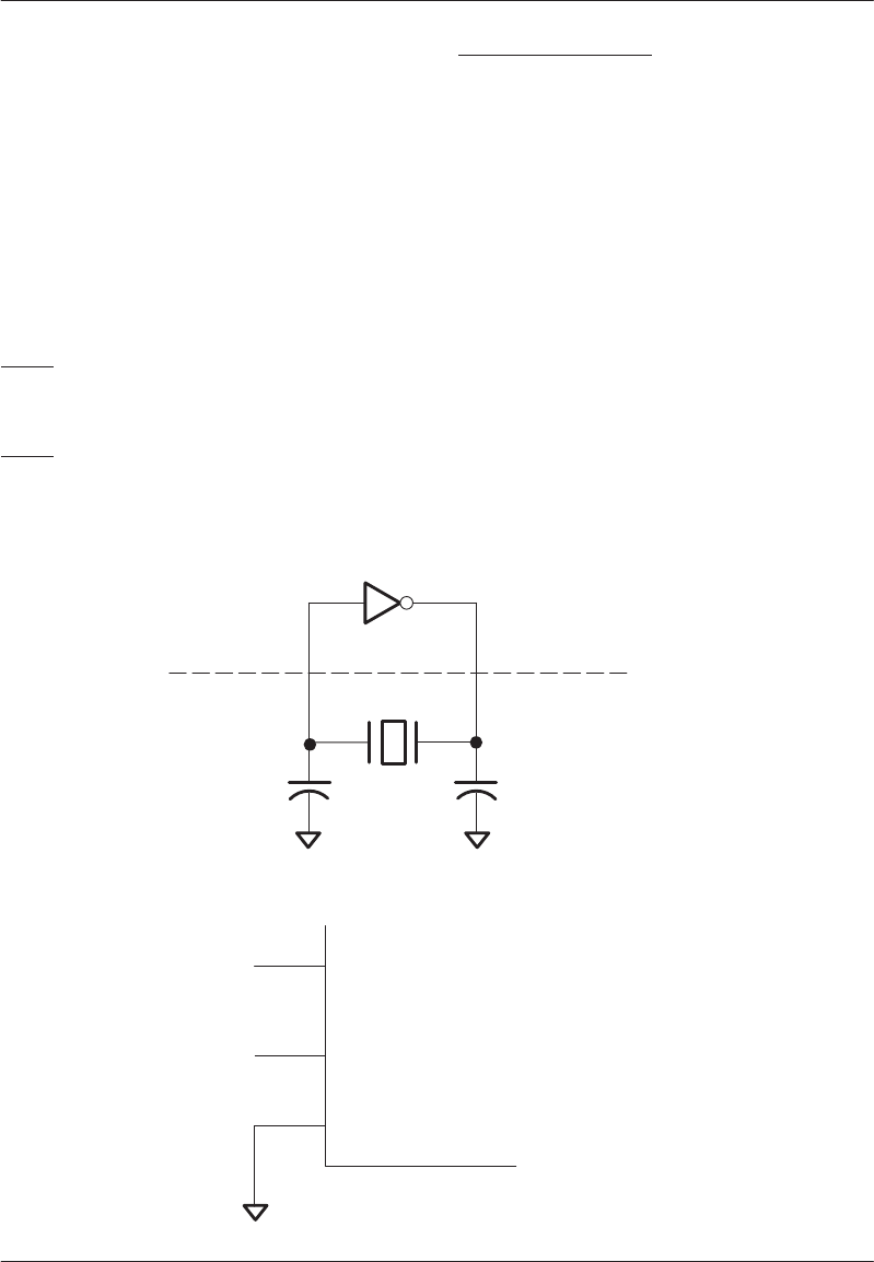
The schematic shown in Figure 15–1 illustrates the re-
quired connections when using a crystal. Typically, the
values of C1 and C2 should both be 33 pF. If a resonator
is used, C1 and C2 should be 47 pF.
XTAL1
Input to the inverting oscillator amplifier and input to the
internal clock generating circuits.
XTAL2
Output from the inverting oscillator amplifier. This pin is
also used to distribute the clock to other devices.
Oscillator Characteristics
XTAL1 and XTAL2 are the input and output, respective-
ly, of an inverting amplifier which can be configured for
use as an on–chip oscillator as shown in Figure 15–1.
The crystal should be parallel resonant, AT cut type.
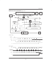
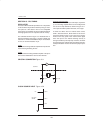
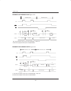
To drive the device from an external clock source,
XTAL1 should be driven, while XTAL2 is left uncon-
nected as shown in Figure 15–2. There are no require-
ments on the duty cycle of the external clock signal
since the input to the internal clocking circuitry is
through a divide–by–two flip–flop. However, minimum
and maximum high and low times specified in the elec-
trical specifications must be met to insure proper opera-
tion.
CRYSTAL CONNECTION Figure 15–1
Soft Micro
XTAL1 XTAL2
33 pF 33 pF
CLOCK SOURCE INPUT Figure 15–2