


USER’S GUIDE
050396 92/173
93
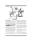
INTERRUPT PRIORITIES
The Secure Microcontroller provides a three priority
interrupt scheme. Multiple priority levels allow higher
priority sources to interrupt lower priority ISRs. The
Power–fail Warning Interrupt automatically has the
highest priority if enabled. The remaining interrupts can
be programmed by the user to either high or low priority.
The priority scheme woks as follows. The ISR for a low
priority source can be interrupted by a high priority
source. A low priority ISR can not be interrupted by
another low priory source. Neither can a high priority
ISR be interrupted by a another high priority source. The
PFW source will interrupt any ISR if activated.
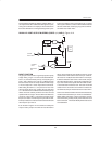
In the case of simultaneous interrupt requests, the mi-
crocontroller has a natural scheme to arbitrate. First, if
high and low priority interrupt requests are received
simultaneously, then the high priority source will be
serviced. If two or more requests from equal priority
sources are received, the following natural priority
scheme will be used to arbitrate.
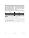
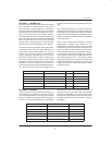
Each interrupt priority is determined by an individual bit
as shown below. Setting the appropriate bit to a logic 1
will cause that interrupt to be high priority.
PRIORITY
FLAG INTERRUPT SOURCE
1 PFW Power–fail Warning
2 IE0 External Interrupt 0
3 TF0 Timer 0 Interrupt
4 IE1 External Interrupt 1
5 TF1 Timer 1 Interrupt
6 RI+TI Serial I/O Interrupt
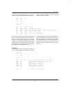
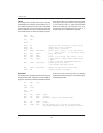
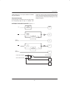
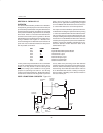
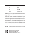
INTERRUPT PRIORITY CONTROL BITS Figure 11–3
Bit Description:
All bits are read/write at any time and are cleared to 0 following any hardware reset.
IP.4: PS
“Serial Port Priority”: Programs Serial Port interrupts for high priority when set to 1. Low priority is
selected when cleared to 0.
IP.3: PT1
“Timer 1 Priority”: Programs Timer 1 interrupt for high priority when set to 1. Low priority is se-
lected when cleared to 0.
IP.2: PX1
“Ext. Int. 1 Priority”: Programs External Interrupt 1 for high priority when set to 1. Low priority is
selected when cleared to 0.
IP.1: PT0
“Timer 0 Priority”: Program Timer 0 interrupt for high priority when set to 1. Low priority is se-
lected when cleared to 0.
IP.0: PX0
“Ext. Int. 0 Priority”: Programs External Interrupt 0 for high priority when set to 1. Low priority is
selected when cleared to 0.