


USER’S GUIDE
050396 32/173
33
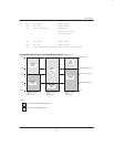
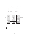
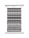
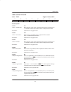
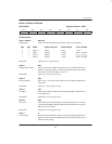
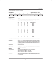
TIMER CONTROL REGISTER
Label: TCON Register Address 088H
D7 D6 D5 D4 D3 D2 D1 D0
TF1 TR1 TF0 TR0 IE1 IT1 IE0 IT0
Bit Description:
TCON.7: TF1
“Timer 1 Overflow Flag”: Status bit set to 1 when Timer 1 overflows from a previous count value of all
1’s. Cleared to 0 when CPU vectors to Timer 1 interrupt service routine.
Initialization: Cleared to 0 on any type of reset.
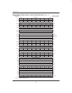
TCON.6: TR1
“Timer 1 Run Control”: When set to a 1 by software, Timer 1 operation will be enabled.
Timer 1 is disabled when cleared to 0.
Initialization: Cleared to 0 on any type of reset.
TCON.5: TF0
“Timer 0 Overflow”: Status bit set to 1 when Timer 0 overflows from a previous count value of all
1’s. Cleared to 0 when CPU vectors to Timer 0 interrupt service routine.
Initialization: Cleared to 0 on any type of reset.
TCON.4: TR0
“Timer 0 Run Control”: When set to a 1 by software, Timer 0 operation is enabled. Timer 0 is dis-
abled when cleared to 0.
Initialization: Cleared to 0 on any type of reset.
TCON.3: IE1
“Interrupt 1 Edge Detect”: Set to 1 to signal when a 1–to–0 transition (IT=1) or a low level (IT=0) has
been detected on the INT1
pin. Cleared to a 0 by hardware when interrupt
processed only if IT1=1.
Initialization: Cleared to 0 on any type of reset.
TCON.2: IT1
“Interrupt 1 Type Select”: When set to 1, 1–to–0 transitions on INT1
will be used to generate interrupt
requests from this pin. When cleared to 0, INT1 is level-activated.
Initialization: Cleared to a 0 on any type of reset.
TCON.1: IE0
“Interrupt 0 Edge Detect”: Set to a 1 to signal when a 1–to–0 transition (IT0=1) or a low level (IT0=0)
has been detected on the INT0
pin. Cleared to a 0 by hardware when inter-
rupt processed only if IT0=1.
Initialization: Cleared to a 0 on any type of reset.