


USER’S GUIDE
050396 17/173
18
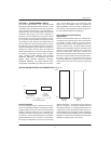
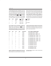
a Partitionable mode (PM=0), the DS5001 can use up
to 64K x 8 SRAM for program and data on its Byte–wide
bus. It can partition this area into program and data
segments on 4K boundaries. The 64K memory space
would consist of two 32K x 8 SRAMs. Each is accessed
by a separate chip enable (CE1
and CE2), but the mi-
crocontroller automatically decodes which is needed.
While the DS5001 can use between one 8K x 8 SRAM
and 4 32K x 8 SRAMs, it does not automatically know
which configuration is used. The Range function deter-
mines how much total memory is connected to the
Byte–wide bus. The user must identify the total RAM
size using the Range bits RG1 and RG0. RG1 is lo-
cated at MCON.3 and RG0 is located at RPCTL.0.
These Range bits are selected during the Bootstrap
Loading process and can not be modified by the ap-
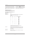
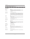
plication software. The Table below shows the Range
values that can be selected when PM=0 (Partitionable).
RG1 RG0 RANGE CE1
ACCESS CE2 ACCESS
1 1 64K 0000–7FFFh 8000–FFFFh
1 0 32K 0000–7FFFh NA
0 1 16K 0000–1FFFh 2000h–3FFFh
0 0 8K 0000–1FFFh NA
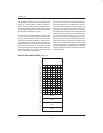
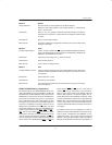
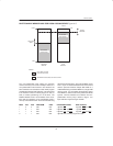
The total RAM space is partitionable, regardless of
which Range is selected. This contrasts with the
DS5000 that allowed partitioning of CE1
only. The
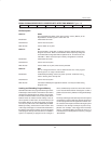
Partition table is shown below. PA3–0 are the four MSBs
of the MCON register (MCON.7–4). Note that the Parti-
tion values do not scale depending on Range. That is, if
a Range of less than 64K is selected, then the partition
settings above the Range should not be unused. The
microcontroller automatically decodes which RAM to
enable, and uses the Partition to decide if this is pro-
gram memory or data memory.
PA3 PA2 PA1 PA0 PARTITION BYTE–WIDE BUS MEMORY MAP
0 0 0 0 0000h 0K PROGRAM, DATA = RANGE
0 0 0 1 1000h 4K PROGRAM, DATA = RANGE – 4K
0 0 1 0 2000h 8K PROGRAM, DATA = RANGE – 8K
0 0 1 1 3000h 12K PROGRAM, DATA = RANGE – 12K
0 1 0 0 4000h 16K PROGRAM, DATA = RANGE – 16K
0 1 0 1 5000h 20K PROGRAM, DATA = RANGE – 20K
0 1 1 0 6000h 24K PROGRAM, DATA = RANGE – 24K
0 1 1 1 7000h 28K PROGRAM, DATA = RANGE – 28K
1 0 0 0 8000h 32K PROGRAM, DATA = RANGE – 32K
1 0 0 1 9000h 36K PROGRAM, 28K DATA
1 0 1 0 A000h 40K PROGRAM, 24K DATA
1 0 1 1 B000h 44K PROGRAM, 20K DATA
1 1 0 0 C000h 48K PROGRAM, 16K DATA
1 1 0 1 D000h 52K PROGRAM, 12K DATA
1 1 1 0 E000h 56K PROGRAM, 8K DATA
1 1 1 1 FFFFh 64K PROGRAM, 0K DATA
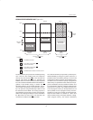
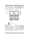
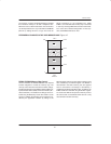
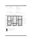
Figure 4–5 illustrates the functional memory map of a
DS5001 series device in Partitionable mode. Note that
like the DS5000, any access that does not correspond
to a Byte–wide bus location is routed to the Expanded
bus Ports 0 and 2.