


28
DataTalker Owner’s Manual
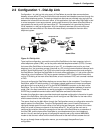
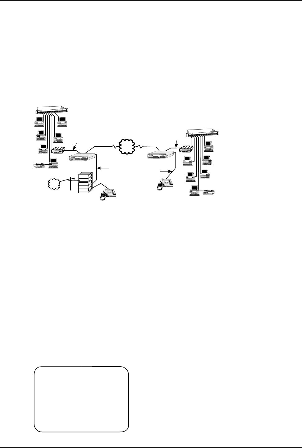
2.4 Configuration 3 - LAN to LAN
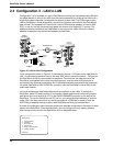
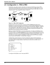
Configuration 3 is an example of a pair of DataTalkers providing the link between two LANs with
the added benefit of voice or fax traffic over the same composite link. Bridging the LANs over a
single high speed composite link expands the capacity of each LAN. The LAN bridge on each
LAN is provided by a router/bridge with a synchronous interface connected to the DataTalker’s
data channel. The composite link could be an internal ISDN terminal adapter, an internal 56K
DSU, or one of a variety of external high speed link devices up to fractional T1 devices. The
additional feature provided by the DataTalkers is free voice or fax traffic without the need to
establish a separate voice connection between the two LANs.
Communications
Server
File Server
Print Server
Printer
Ethernet
Concentrator
LAN 1
Composite Link
PDN
LAN 2
PBX
Trunk
Trunk
Station
Trunk
Station
PSTN
Voice/Fax
Channel
Voice/Fax
Channel
Telephone
Telephone
File Server
Print Server
LAN PC
LAN PC
LAN PC
Printer
Communications
Server
Ethernet
Concentrator
LAN PC
LAN PC
LAN PC
Router/Bridge
T
e
c
h
Sy
stems
®
Router/Bridge
T
e
c
h
S
ys
tem
s
®
Sync Data
Channel
Sync Data
Channel
DataTalker
COMPOSITE
LINK
STATUS
VOICE /
FAX 1
DATA/
COMMAND
ORIG
101 MDM/TA
RXTFCRRDTMV35 EXTMDMDSU
CDRCVXMTCTS56RTSNSOOS
28.8 OHDBUP
TA
DTR
2B
FXSFXO E&MFAXXMT RCVXSGRSGCOMXMTRCVFC
VOICE /
FAX 2
RSGXSGRCVXMTFAXE&MFXOFXS
Data / Voice / Fax Concentrator
DataTalker
COMPOSITE
LINK
STATUS
VOICE /
FAX 1
DATA/
COMMAND
ORIG
101 MDM/TA
RXTFCRRDTMV35 EXTMDMDSU
CDRCVXMTCTS56RTSNSOOS
28.8 OHDBUP
TA
DTR
2B
FXSFXO E&MFAXXMT RCVXSGRSGCOMXMTRCVFC
VOICE /
FAX 2
RSGXSGRCVXMTFAXE&MFXOFXS
Data / Voice / Fax Concentrator
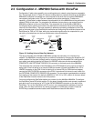
Figure 2-3. LAN to LAN Configuration
In the configuration shown in Figure 2-3, the voice/fax channel 1 FXO port on the DataTalker at
LAN 1 is connected to a station card on the local PBX, and the voice/fax channel 1 FXS port on
the DataTalker at LAN 2 is connected to a telephone. On both ends, the data channel of the
DataTalker is connected to the router’s synchronous port, and the router’s Ethernet port is
connected to the Ethernet concentrator. An RJ-48 telephone cable connected to the composite
link at the DataTalker’s DSU/TA DIGITAL connector links the DataTalker’s internal DSU to the
public data network.
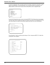
You must configure the DataTalkers before you connect them to the LANs. To configure a
DataTalker, place DIP switch position 3 in the down (closed) position and connect a command
port device such as a terminal or a PC to the DATA/COMMAND connector on the back of the
DataTalker. Turn on the DataTalker and PC and run your communications software in terminal
mode. (Set it for direct connection at a serial port speed of 19,200 bps or slower.) Press the
ENTER key to establish communications with DataTalker
and bring up the Main Menu.
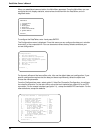
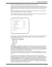
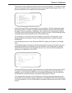
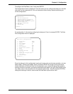
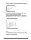
A series of configuration menus provides simple and complete configuration information for each
aspect of the DataTalker. From the Main Menu, you can configure the unit, display statistics,
reset various functions within the DataTalker, and run diagnostic tests:
Main Menu
1 - Configurations
2 - Statistics
3 - Reset Options
4 - Diagnostics
5 - Exit Command Mode
6 - QUICK SETUP
Selection : _