


58
DataTalker Owner’s Manual
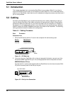
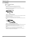
External Modem, DSU, or ISDN Terminal Adapter
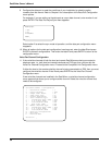
3 If the external device has an RS232 interface, connect the composite link cable supplied with
the DataTalker from the EXTERNAL COMPOSITE RS232C/V.35 connector on the back
panel to the external device.
MODEM
DSU/TA
DIAL-UP LEASED DIGITAL
VOICE/FAX CHANNEL 1
FXO FXS
EXTERNAL COMPOSITE
DATA/COMMAND
RS232C/V.35
E&M
INTERNAL COMPOSITE
POWER
GND
To External
Device
Composite
Link Cable
Figure 5-6. External Modem, DSU, or Terminal Adapter Connection
If the external device has a V.35 interface, connect a V.35 interface adapter cable (a cable
with a 34-pin Winchester male connector on one end and a DB-25S connector on the other
end) from the EXTERNAL COMPOSITE RS232C/V.35 connector to the external device. You
can order a V.35 interface adapter cable from Multi-Tech (part number 90056210).
If the external device has a V.35 interface, you must move the V.35 shunt from its default
RS232 position to the V.35 position. See Table 5-2 for the procedure on how to move the
shunt.
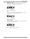
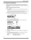
Data Channel
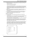
4 If you are connecting the data channel to an asynchronous device, such as a PC or other
type of host, connect an RS232C cable from the DATA/COMMAND connector on the
DataTalker to the serial port of the async device.
MODEM
DSU/TA
DIAL-UP LEASED DIGITAL
VOICE/FAX CHANNEL 1
FXO FXS
EXTERNAL COMPOSITE
DATA/COMMAND
RS232C/V.35
E&M
INTERNAL COMPOSITE
POWER
GND
DATA/COMMAND
Connector
RS232 Cable
Figure 5-7. Data Channel Connection
If you are connecting the data channel to a sync device, connect a cable appropriate for a
synchronous interface from the DATA/COMMAND connector on the DataTalker to the
appropriate connector on the sync device.
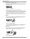
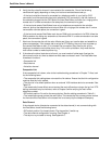
Voice/Fax Channel
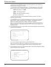
5 If you are connecting the voice/fax channel to a station device (a normal telephone, a KTS
telephone, or a fax machine), connect an RJ-11 phone cable from the VOICE/FAX
CHANNEL FXS connector on the DataTalker to the station instrument.
MODEM
DSU/TA
DIAL-UP LEASED DIGITAL
VOICE/FAX CHANNEL 1
FXO FXS
EXTERNAL COMPOSITE
DATA/COMMAND
RS232C/V.35
E&M
INTERNAL COMPOSITE
POWER
GND
VOICE/FAX CHANNEL 2
RJ-11
Telephone
Cable
VOICE/FAX
CHANNEL 1
FXS Connector
8
9
7
4
5
6
3
2
1
#
0
*
Figure 5-8. Telephone Connection