


48
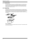
DataTalker Owner’s Manual
4.7 Configuration Procedure
Table 4-1. Configuration Procedure
Step Procedure
1 Review the configuration considerations for the data port, the voice/fax channel, and the
composite link in the previous sections.
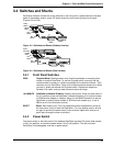
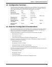
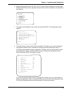
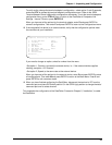
2 Place DIP switch position 3 in the down (closed) position to enable the command port.
MODEM
DSU/TA
DIAL-UP LEASED DIGITAL
VOICE/FAX CHANNEL 1
FXO FXS
EXTERNAL COMPOSITE
DATA/COMMAND
RS232C/V.35
E&M
INTERNAL COMPOSITE
POWER
GND
DIP
Switch
3 Desktop version: Connect the DC power supply shipped with the DataTalker to the power
connector on the back panel and to the AC outlet.
Rack-mounted version: Insert the DataTalker into a RackTalker rack.
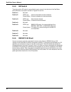
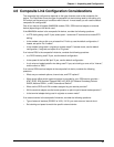
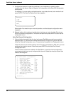
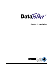
4 Connect a terminal or PC running communications software to the DATA/COMMAND
connector on the back panel of the DataTalker. Use an appropriate RS232 cable to connect
the DATA/COMMAND connector to your PC’s serial port. The terminal or PC serial port may
be labeled COM1, COM2, or Serial Port. The DATA/COMMAND connector has a DCE
physical interface.
MODEM
DSU/TA
DIAL-UP LEASED DIGITAL
VOICE/FAX CHANNEL 1
FXO FXS
EXTERNAL COMPOSITE
DATA/COMMAND
RS232C/V.35
E&M
INTERNAL COMPOSITE
POWER
GND
DATA/COMMAND
Connector
RS232 Cable
Note: Any cables connected to the computer should be shielded to reduce interference.
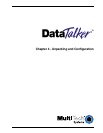
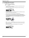
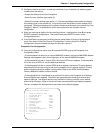
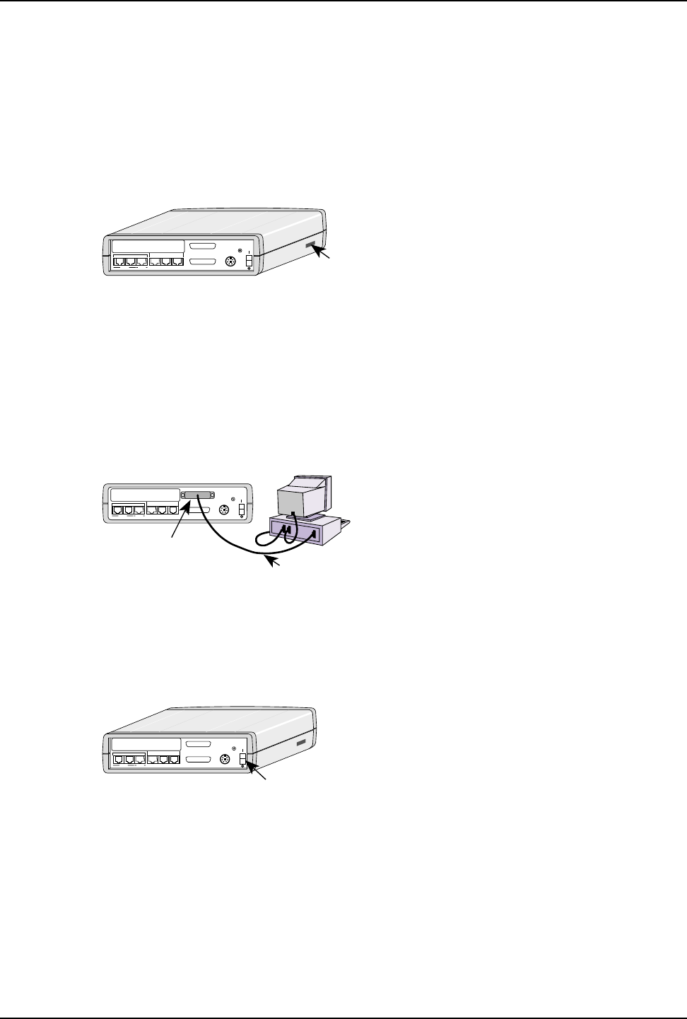
5 Desktop version: Apply power to the DataTalker by placing the power switch on the back
panel in the on (I) position.
Rack-mounted version: Apply power to the RackTalker rack if it is not already on.
MODEM
DSU/TA
DIAL-UP LEASED DIGITAL
VOICE/FAX CHANNEL 1
FXO FXS
EXTERNAL COMPOSITE
DATA/COMMAND
RS232C/V.35
E&M
INTERNAL COMPOSITE
POWER
GND
Power
Switch