


Appendix B Common Questions
© National Instruments Corporation B-5 NI 6115/6120 User Manual
Timing and Digital I/O
What types of triggering can be hardware-implemented on the
NI 6115/6120?
Hardware digital and analog triggering are both supported on the
NI 6115/6120.
If I’m using one of the general-purpose counter/timers on the
NI 6115/6120, but I do not see the counter/timer output on the I/O
connector, what am I doing wrong?
If you are using NI-DAQ or LabWindows/CVI, you must configure the
output line to output the signal to the I/O connector. Use the
Select_Signal call in NI-DAQ to configure the output line. By default,
all timing I/O lines except EXTSTROBE* are high-impedance.
What are the PFIs and how do I configure these lines?
PFIs are Programmable Function Inputs. These lines serve as connections
to virtually all internal timing signals.
If you are using NI-DAQ or LabWindows/CVI, use the
Select_Signal
function to route internal signals to the I/O connector, route external signals
to internal timing sources, or tie internal timing signals together.
If you are using NI-DAQ with LabVIEW and you want to connect external
signal sources to the PFI lines, you can use AI Clock Config, AI Trigger
Config, AO Clock Config, AO Trigger and Gate Config, and Counter Set
Attribute advanced-level VIs to indicate which function the connected
signal serves. Use the Route Signal VI to enable the PFI lines to output
internal signals.
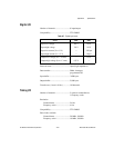
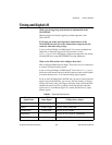
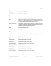
Table B-1. Signal Name Equivalencies
Hardware
Signal Name
LabVIEW
Route Signal
NI-DAQ Select_Signal
TRIG1 AI Start Trigger ND_IN_START_TRIGGER
TRIG2 AI Stop Trigger ND_IN_STOP_TRIGGER
STARTSCAN AI Scan Start ND_IN_SCAN_START
SISOURCE — ND_IN_SCAN_CLOCK_TIMEBASE
CONVERT* AI Convert ND_IN_CONVERT