


Chapter 4 Connecting Signals
NI 6115/6120 User Manual 4-12 ni.com
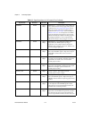
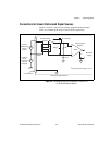
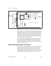
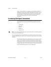
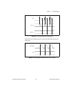
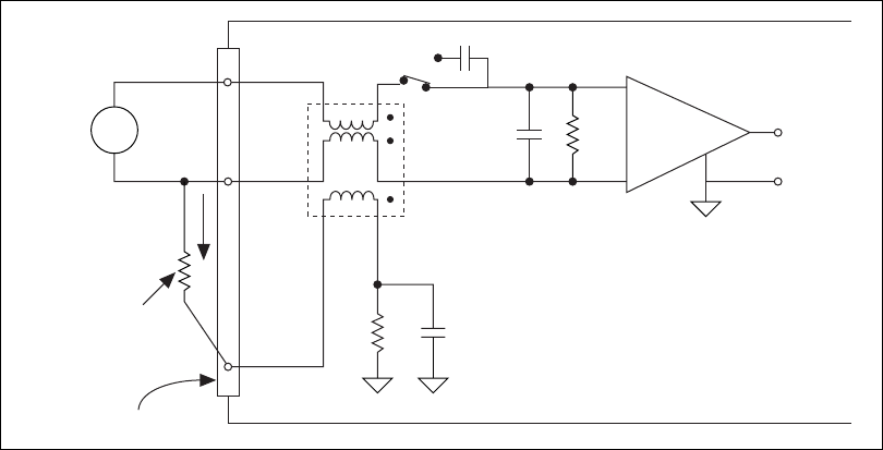
Figure 4-5. Differential Input Connections on the NI 6120 for Nonreferenced Signals
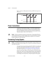
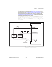
Figures 4-4 and 4-5 show a bias resistor connected between ACH0– and the
floating signal source ground. This resistor provides a return path for the
±200 pA bias current. A value of 10 kΩ to 100 kΩ is usually sufficient.
If you do not use the resistor and the source is truly floating, the source is
not likely to remain within the common-mode signal range of the PGIA,
and the PGIA saturates, causing erroneous readings. You must reference
the source to the respective channel ground.
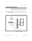
Common-mode rejection might be improved by using another bias resistor
from the ACH0+ input to ACH0GND. This connection gives a slight
measurement error due to the voltage divider formed with the output
impedance of the floating source, but it also gives a more balanced input for
better common-mode rejection.
Common-Mode Signal Rejection Considerations
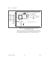
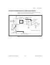
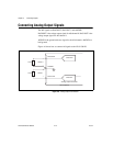
Figures 4-2 and 4-3 show connections for signal sources that are already
referenced to some ground point with respect to the NI 6115/6120. In
theory, the PGIA can reject any voltage caused by ground-potential
differences between the signal source and the device. In addition, with
pseudodifferential input connections, the PGIA can reject common-mode
noise pickup in the leads connecting the signal sources to the device.
+
–
V
m
100 pF* 1 M*
50 Ω 0.1 µF
High-Frequency
Common Mode Choke
ACH0+
ACH0–
ACH0GND
PGIA
Instrumentation
Amplifier
*10 kΩ40 pf for ranges > ±10 V
Floating
Signal
Source
AC Coupling
Measured
Voltage
V
s
+
–
Bias
Resistor
(see text)
I/O Connector
Bias
Current
Return
Paths
+
–