


Chapter 3 Hardware Overview
© National Instruments Corporation 3-11 NI 6115/6120 User Manual
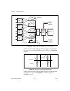
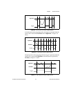
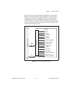
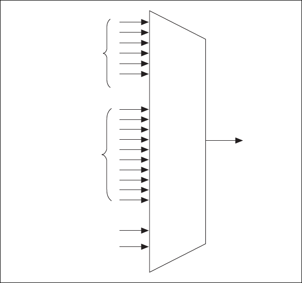
configurable. For example, Figure 3-11 shows the signal routing
multiplexer for controlling the STARTSCAN signal.
Figure 3-11. STARTSCAN Signal Routing
This figure shows that STARTSCAN can be generated from a number of
sources, including the external signals RTSI<0..6> and PFI<0..9> and the
internal signals Scan Interval Counter TC and GPCTR0_OUT.
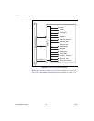
Many of these timing signals are also available as outputs on the RTSI pins,
as indicated in the RTSI Triggers section later in this chapter, and on the
PFI pins, as indicated in Chapter 4, Connecting Signals.
RTSI Trigger <0..6>
PFI<0..9>
STARTSCAN
Scan Interval Counter TC
GPCTR0_OUT