


Chapter 4 Connecting Signals
NI 6115/6120 User Manual 4-4 ni.com
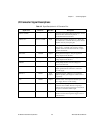
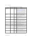
PFI0/TRIG1 DGND Input
Output
PFI0/Trigger 1—As an input, this is either a PFI or the
source for the hardware analog trigger. PFI signals are
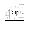
explained in the Connecting Timing Signals section
later in this chapter. The hardware analog trigger is
explained in the Analog Trigger section of Chapter 3,
Hardware Overview. As an output, this is the TRIG1
signal. In posttrigger DAQ sequences, a low-to-high
transition indicates the initiation of the DAQ sequence.
In pretrigger applications, a low-to-high transition
indicates the initiation of the pretrigger conversions.
PFI1/TRIG2 DGND Input
Output
PFI1/Trigger 2—As an input, this is a PFI. As an
output, this is the TRIG2 signal. In pretrigger
applications, a low-to-high transition indicates the
initiation of the posttrigger conversions. TRIG2 is not
used in posttrigger applications.
PFI2/CONVERT* DGND Input
Output
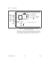
PFI2/Convert—As an input, this is a PFI. As an output,
this is the CONVERT* signal. A high-to-low edge on
CONVERT* indicates that an A/D conversion is
occurring.
PFI3/GPCTR1_SOURCE DGND Input
Output
PFI3/Counter 1 Source—As an input, this is a PFI. As
an output, this is the GPCTR1_SOURCE signal. This
signal reflects the actual source connected to the
general-purpose counter 1.
PFI4/GPCTR1_GATE DGND Input
Output
PFI4/Counter 1 Gate—As an input, this is a PFI. As an
output, this is the GPCTR1_GATE signal. This signal
reflects the actual gate signal connected to the
general-purpose counter 1.
GPCTR1_OUT DGND Output Counter 1 Output—This output is from the
general-purpose counter 1 output.
PFI5/UPDATE* DGND Input
Output
PFI5/Update—As an input, this is a PFI. As an output,
this is the UPDATE* signal. A high-to-low edge on
UPDATE* indicates that the AO primary group is being
updated.
PFI6/WFTRIG DGND Input
Output
PFI6/Waveform Trigger—As an input, this is a PFI.
As an output, this is the WFTRIG signal. In timed
AO sequences, a low-to-high transition indicates the
initiation of the waveform generation.
PFI7/STARTSCAN DGND Input
Output
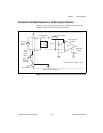
PFI7/Start of Scan—As an input, this is a PFI. As an
output, this is the STARTSCAN signal. This pin pulses
once at the start of each AI scan in the interval scan.
A low-to-high transition indicates the start of the scan.
Table 4-2. Signal Descriptions for I/O Connector Pins (Continued)
Signal Name Reference Direction Description