


Chapter 4 Connecting Signals
NI 6115/6120 User Manual 4-34 ni.com
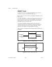
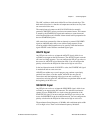
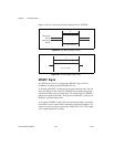
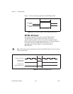
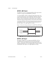
Figure 4-31 shows the timing requirements for GPCTR0_GATE.
Figure 4-31. GPCTR0_GATE Signal Timing in Edge-Detection Mode
GPCTR0_OUT Signal
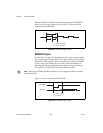
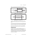
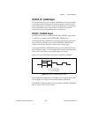
This signal is available as an output on the GPCTR0_OUT pin.
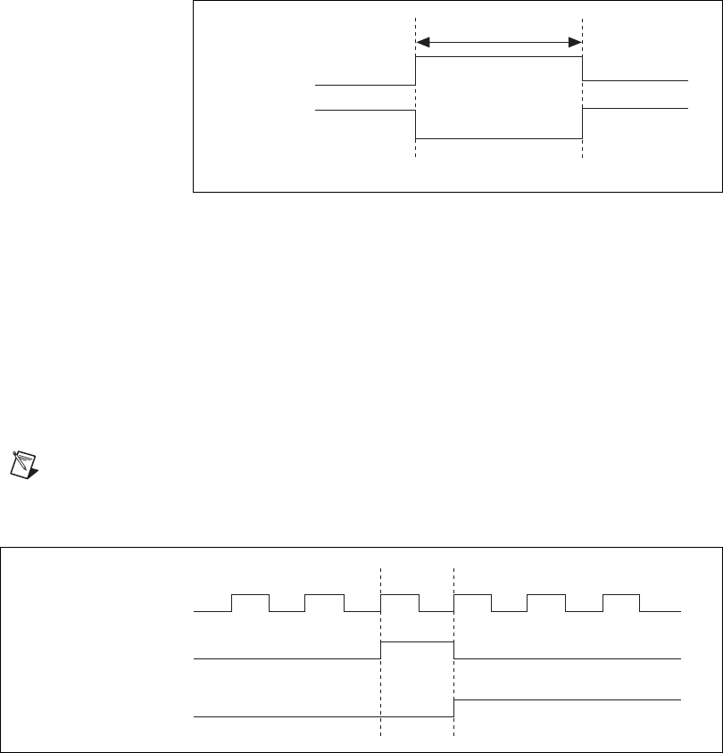
The GPCTR0_OUT signal reflects the terminal count (TC) of
general-purpose counter 0. You have two software-selectable output
options: pulse on TC and toggle output polarity on TC. The output polarity
is software-selectable for both options. This output is set to
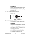
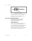
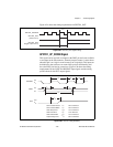
high-impedance at startup. Figure 4-32 shows the timing of
GPCTR0_OUT.
Note When using external clocking mode with correlated DIO, this pin is used as an input
for the external clock.
Figure 4-32. GPCTR0_OUT Signal Timing
Rising-Edge
Polarity
Falling-Edge
Polarity
t
w
= 10 ns minimum
t
w
GPCTR0_SOURCE
GPCTR0_OUT
(Pulse on TC)
GPCTR0_OUT
(Toggle output on TC)
TC