


Chapter 4 Connecting Signals
NI 6115/6120 User Manual 4-16 ni.com
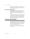
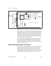
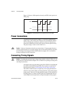
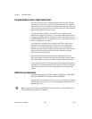
Figure 4-7 shows DIO<0..3> configured for digital input and DIO<4..7>
configured for digital output. Digital input applications include receiving
TTL signals and sensing external device states such as the switch state
shown in Figure 4-7. Digital output applications include sending TTL
signals and driving external devices such as the LED shown
in Figure 4-7.
Correlating DIO Signal Connections
You can correlate DIO and AI/AO operations to the same clock on the
NI 6115/6120. You can use any of the following signals as the clock
source:
• AI Scan Start
• AO Update
•GPCTR
• RTSI<0..5>
• External Clock
Notes To use either of the GPCTR signals or the external clock to clock DIO operations,
you must use one RTSI<0..5> pin.
To use an external clock for correlated DIO, the clock must have input on the Counter 0
output pin (GPCTR0_OUT). In this case, be sure that this counter is not used in any other
operation.
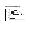
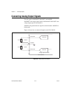
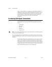
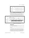
The following timing diagrams illustrate the use of these signals as clock
sources. You can software-configure DIO operations for either rising or
falling edge on whichever clock you choose as the source. Figure 4-8 shows
any clock signal, in general, driving two separate groups of lines configured
for digital input (DI) and DO. The DI operation is using the rising edge of
the clock and the DO operation is using its falling edge.