


Chapter 4 Connecting Signals
NI 6115/6120 User Manual 4-22 ni.com
Refer to Chapter 3, Hardware Overview, for more information on analog
triggering.
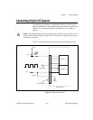
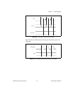
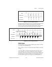
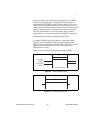
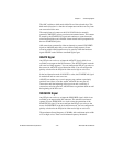
As an output, TRIG1 reflects the action that initiates a DAQ sequence even
if another PFI is externally triggering the acquisition. The output is an
active high pulse with a pulse width of 25 to 50 ns. This output is set to
high-impedance at startup.
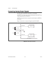
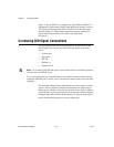
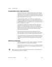
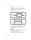
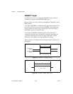
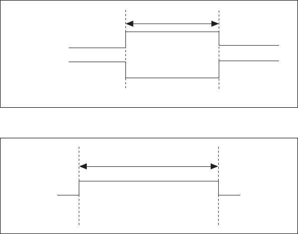
Figures 4-14 and 4-15 show the timing requirements for TRIG1.
Figure 4-14. TRIG1 Input Signal Timing
Figure 4-15. TRIG1 Output Signal Timing
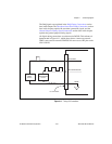
The device also uses TRIG1 to initiate pretriggered DAQ operations. In
most pretriggered applications, TRIG1 is generated by a software trigger.
Refer to the TRIG2 signal description for a complete description of the use
of TRIG1 and TRIG2 in a pretriggered DAQ operation.
TRIG2 Signal
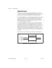
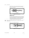
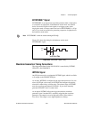
Any PFI pin can receive as an input the TRIG2 signal, which is available
as an output on the PFI1/TRIG2 pin. Refer to Figure 4-13 for the
relationship of TRIG2 to the DAQ sequence.
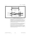
As an input, TRIG2 is configured in the edge-detection mode. You can
select any PFI pin as the source for TRIG2 and configure the polarity
Rising-Edge
Polarity
Falling-Edge
Polarity
t
w
= 10 ns minimum
t
w
t
w
t
w
= 25 – 50 ns