


Appendix B Common Questions
NI 6115/6120 User Manual B-6 ni.com
Caution If you enable a PFI line for output, do not connect any external signal source to it;
if you do, you can damage the device, the computer, and the connected equipment.
What are the power-on states of the PFI and DIO lines on the
I/O connector?
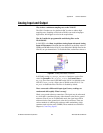
At system power-on and reset, both the PFI and DIO lines are set to
high-impedance by the hardware. Hence, the device circuitry is not actively
driving the output either high or low. However, these lines may have pull-up
or pull-down resistors connected to them as shown in Table 4-5, Digital I/O
Signal Summary. These resistors weakly pull the output to either a
logic-high or logic-low state. For example, DIO(0) is in the
high-impedance state after power on, and Table 4-5 shows that there is a
50 kΩ pull-up resistor. This pull-up resistor sets the DIO(0) pin to a logic
high when the output is in a high-impedance state.
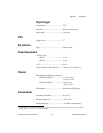
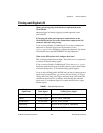
AIGATE — ND_IN_EXTERNAL_GATE
WFTRIG AO Start Trigger ND_OUT_START_TRIGGER
UPDATE* AO Update ND_OUT_UPDATE
UISOURCE — ND_OUT_UPDATE_CLOCK_TIMEBASE
AOGATE — ND_OUT_EXTERNAL_GATE
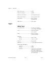
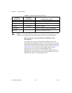
Table B-1. Signal Name Equivalencies (Continued)
Hardware
Signal Name
LabVIEW
Route Signal
NI-DAQ Select_Signal