


Chapter 3 Hardware Overview
NI 6115/6120 User Manual 3-6 ni.com
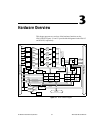
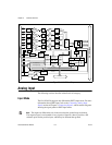
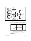
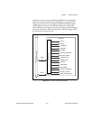
Figure 3-3. Analog Trigger Block Diagram for the NI 6115/6120
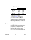
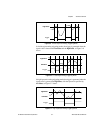
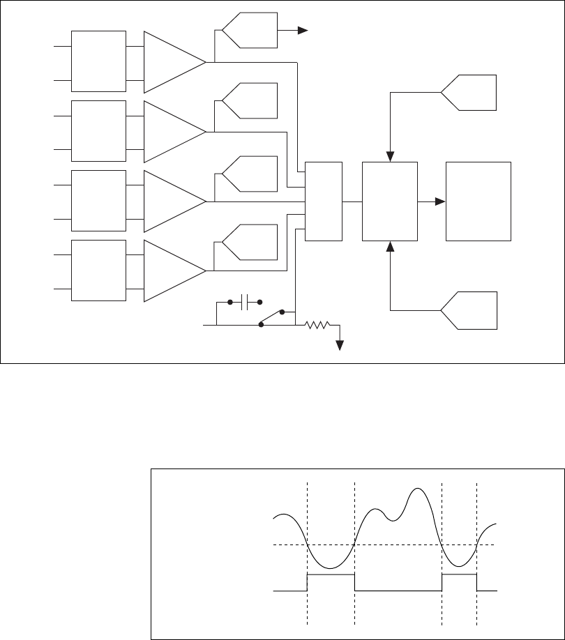
In below-low-level analog triggering mode, the trigger is generated when
the signal value is less than lowValue, as shown in Figure 3-4. HighValue
is unused.
Figure 3-4. Below-Low-Level Analog Triggering Mode
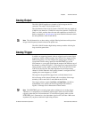
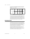
In above-high-level analog triggering mode, the trigger is generated when
the signal value is greater than highValue, as shown in Figure 3-5.
LowValue is unused.
PGIA
Analog
Input
CH0
+
–
ADC
ADC
ADC
DAQ-STC
Analog
Trigger
Circuit
Mux
PGIA
Analog
Input
CH1
+
–
PGIA
Analog
Input
CH2
+
–
PGIA
Analog
Input
CH3
+
–
ADC
PFI0/TRIG1
Digital Data
AC Couple
10 k
Trigger
DAC
Trigger
DAC
highValue
lowValue
lowValue
Trigger