


Chapter 1 Installing and Configuring the SCXI-1127/1128
© National Instruments Corporation 1-7 SCXI-1127/1128 User Manual
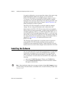
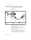
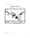
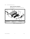
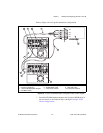
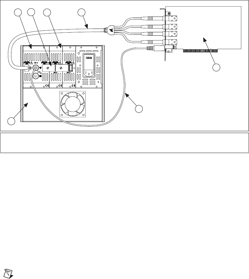
Figure 1-3.
4-Slot Configuration Parts Locator Diagram
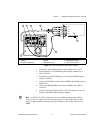
1. Install the 2-slot HVAB-backplane adapter behind slots 3 and 4.
2. Install additional 1-slot HVAB-backplane adapters behind slots 1
and 2 if needed.
3. Install the 8-position HVAB plugs to connect the HVAB-backplane
adapters as needed.
4. Connect the HV8-BAN4 cable from the DMM to the HVAB connector
behind slot 4.
5. Connect the SH9MD-9MD cable from the DMM to the AUX IN
connector.
6. You can install any additional SCXI-1127/1128 modules in any slot
that has an HVAB-backplane adapter behind it.
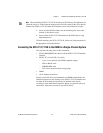
Note
An SCXI-1127/1128 is required in slot 4 to establish communication with the
chassis. If slot 4 is empty, the system will not operate. It is this module that you must
specify in Measurement & Automation Explorer (MAX) as the module cabled to the
DMM.
1 2-Slot HVAB-Backplane
Adapter
2 8-Position HVAB Plug
3 1-Slot HVAB-Backplane
Adapter
4 HV8-BAN4 Cable
5 NI 4060 for PCI
6 SH9MD-9MD Cable
7 4-Slot SCXI Chassis
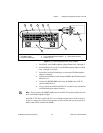
AB0+
AB0–
AB2+
AB2–
5
6
7
2
4
1
3