


Chapter 2 Using the SCXI-1127/1128
SCXI-1127/1128 User Manual 2-28 ni.com
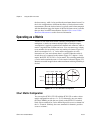
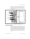
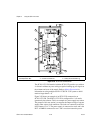
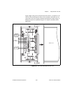
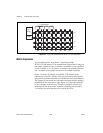
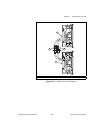
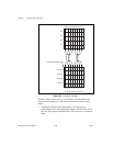
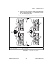
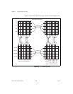
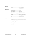
Figure 2-25 shows the schematic of the 8 × 16 matrix shown in Figure 2-24.
Figure 2-25. 8
×
16 Matrix Schematic
Cable #6
Cable #1
Cable #5
Cable #3
Cable #2
Cable #4
Terminal Block Boundary
SCXI-1127/SCXI-1332 #1
R0
R1
R2
R3
R4 (R0)
C0
C1
C2
C3
C4
C5
C6
C7
C8 (C0)
C9 (C1)
C10 (C2)
C11 (C3)
C12 (C4)
C13 (C5)
C14 (C6)
C15 (C7)
R5 (R1)
R6 (R2)
R7 (R3)
SCXI-1127/SCXI-1332 #2
SCXI-1127/SCXI-1332 #3
SCXI-1127/SCXI-1332 #4