


Chapter 2 Using the SCXI-1127/1128
© National Instruments Corporation 2-9 SCXI-1127/1128 User Manual
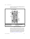
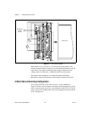
negative screw terminals and sensed via 1B positive and negative screw
terminals.
Note
OUT0± and OUT2± are also referred to as COM0± in a 4-wire configuration.
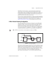
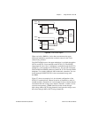
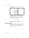
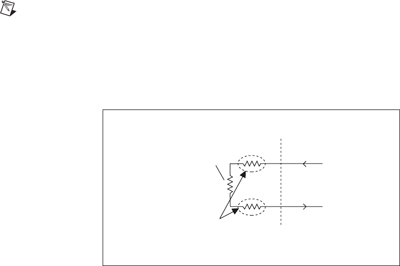
4-Wire versus 2-Wire Resistance Measurement
The primary advantage of using a 4-wire configuration is that it has greater
accuracy than a 2-wire configuration while making resistance
measurements. Figure 2-8 shows signal connections for a 2-wire resistance
measurement of a resistor R
1
.
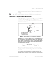
Figure 2-8.
Signal Connections for a 2-Wire Resistance Measurement
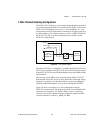
When measuring R
1
in a 2-wire configuration, the voltmeter measures not
only voltage across R
1
due to the excitation current (of the voltmeter) but
also the voltages developed across the parasitic resistance of the voltmeter
cables. When the resistance is finally calculated, these parasitic voltages
make the measurement inaccurate:
Therefore, in a 2-wire resistance measurement, the voltmeter ends up
measuring a resistance that includes the parasitic resistance of the cables
and switches.
To overcome this problem—to eliminate the parasitic resistance of the
connecting cables—a voltmeter uses two sets of cables, one for excitation
V
SENSE
+
2-Wire
Measurement
V
parasitic
V
parasitic
V
R
1
R
1
I
EX
I
EX
V
SENSE
–
Parasitic resistance of
the cables connecting
the resistance to the
measurement device
R
1
measured
2V
parasitic
V
R
1
+
I
EX
---------------------------------------2R
parasitic
R
1
+==