


Chapter 2 Using the SCXI-1127/1128
© National Instruments Corporation 2-15 SCXI-1127/1128 User Manual
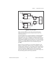
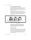
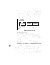
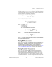
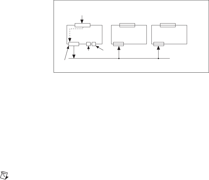
The module to which you connected your external DMM trigger signals is
referred to as the cabled module. If you add additional SCXI-1127/1128
modules to your system, it is not necessary to cable the VMC signal to each
module. You can bus the VMC signal onto the SCXI backplane (Trig 0),
allowing other modules to be triggered as shown in Figure 2-13. These
additional modules are referred to as non-cabled modules because they do
not require the VMC to be connected directly to them.
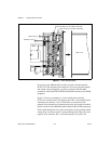
Figure 2-13.
Cabling an External DMM
Handshaking Scanning
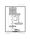
The SCXI-1127/1128 supports a handshaking scanning mode. This is
implemented using the standard VMC/SCANADVD handshaking scheme.
In this mode, the multiplexer responds to every EXT_TRIG_IN trigger by
advancing the multiplexer to the next channel, waiting for the multiplexer
to settle, and then sending a scanner advanced pulse out on a SCANADVD
output trigger back to the DMM.
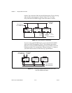
For example, you can connect the VMC of the DMM to the
SCXI-1127/1128 via a screw terminal labeled EXT_TRIG_IN on the
SCXI-1331 terminal block. You must also connect the SCANADVD signal
from the SCXI-1331 terminal block to your DMM external trigger input.
Note
If the external DMM has an internal pull-up on its external trigger input, you need
to configure the SCANADVD signal of the SCXI-1127/1128 as a negative going pulse.
If the external DMM has an internal pull-down on its external trigger input, you need to
configure the SCANADVD signal of the SCXI-1127/1128 as a positive going pulse.
The module to which you connected your external DMM trigger signals is
referred to as the cabled module. If you add additional SCXI-1127/1128
modules to your system, it is not necessary to cable the VMC to each
Trig 0 (Backplane)
Backplane
Connector
Communication
Connection
HVAB
Connector
Cabled
SCXI-1127/1128
EXT_TRIG_IN
From DMM VMC
SCXI Module
SCXI Module