Chapter 2 Using the SCXI-1127/1128
SCXI-1127/1128 User Manual 2-20 ni.com
the best accuracy, while 1-wire provides the maximum channel count. Use
the 4-wire configuration to eliminate the effects of lead resistance on the
measurement. Since the lead resistance is typically small when compared
with the thermistor range, the impact of the lead resistance error is smaller
than you have in an RTD measurement. See the 4-Wire versus 2-Wire
Resistance Measurement section for more information.
Operating as a Matrix
A matrix is one of the most flexible switching configurations. Unlike a
multiplexer, a matrix can connect multiple inputs to multiple outputs.
A multiplexer is typically organized into channels and commons, while a
matrix is organized into columns and rows. You can connect any column
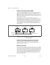
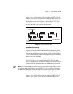
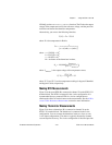
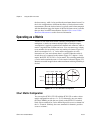
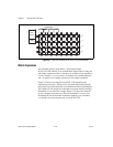
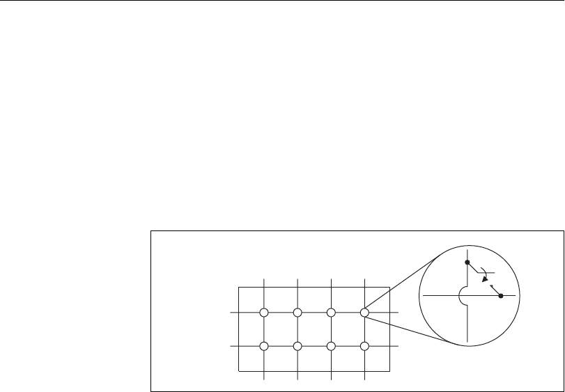
to any number of rows and any row to any number of columns. Figure 2-17
shows an example of a 2 × 4, 1-wire matrix configuration. At each
intersection of a row and column, there is a switch. When the switch is
closed, the row is connected to the column. Figure 2-17 depicts a 1-wire
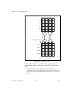
matrix; the SCXI-1127/1128 is a 2-wire matrix. The switching method for
a 2-wire matrix remains the same. A 2-wire matrix is shown in Figure 2-21.
Matrices are useful in applications where maximum switching flexibility is
desired.
Figure 2-17.
2
×
4, 1-Wire Matrix Configuration
32
×
××
×
1 Matrix Configuration
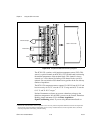
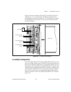
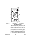
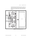
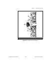
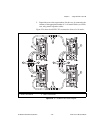
You can use the SCXI-1127/1128 with the SCXI-1331 to make various
matrix configurations such as a 1 × 32, 32 columns by one row, matrix.
OUT0± (COM0±) provide the row signals on the SCXI-1331 terminal
block. Screw terminals for 2-wire channel 0 provide access to column 0 of
the 1 × 32 matrix. Similarly, the screw terminals for channel x provides
access to column x.
Row 0
Row 1
Col 1 Col 2 Col 3 Col 4


