


Chapter 2 Using the SCXI-1127/1128
SCXI-1127/1128 User Manual 2-14 ni.com
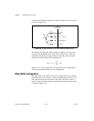
Hardware-Timed Scanning Using a DMM
When using a DMM with the SCXI-1127/1128, synchronous mode is the
only mode in which the DMM and the SCXI-1127/1128 operate. The
DMM issues a trigger to advance the multiplexer at regular intervals. The
DMM and the software guarantee that the switch has fully settled before the
next measurement is taken.
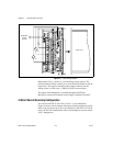
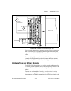
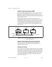
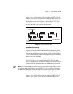
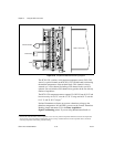
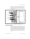
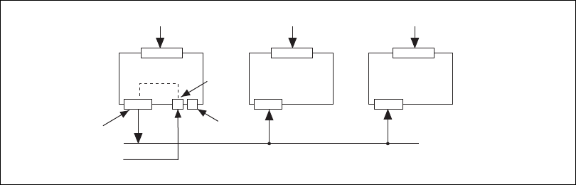
The module that connects directly to the digital connector on the
HVAB-backplane adapter is referred to as the cabled module. If you add
additional SCXI-1127/1128 modules to your system the trigger is bused
over the SCXI backplane (Trig 0) allowing other modules to be triggered,
as shown in Figure 2-12. These additional modules are referred to as
non-cabled modules because they do not require the DMM to be cabled
directly to them.
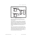
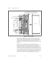
Figure 2-12.
Cabling a DMM and Using the TRIG0 to Bus the VMC/EXT_TRIG_IN
to Non-Cabled Modules
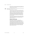
Hardware-Timed Scanning Using External Instruments
When using the SCXI-1127/1128 with an external measurement
instrument, you can use either synchronous or handshaking mode to
advance the SCXI-1127/1128.
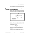
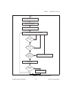
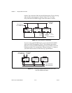
Synchronous Scanning
In the synchronous scanning mode, the measuring device such as a DMM
issues a trigger, voltmeter complete (VMC), to advance the multiplexer at
regular intervals. Each interval must be at least 10 ms to guarantee that the
switch has fully settled before the next measurement is taken. For example,
you can connect the VMC of your DMM to the SCXI-1127/1128 via a
screw terminal labeled EXT_TRIG_IN (external trigger input) on the
SCXI-1331 terminal block.
Trig 0 (Backplane)
RSC
Backplane
Connector
HVAB
Connector
Front Connector
From
DMM AUX
SCXI Module SCXI Module
Front Connector Front Connector