


Chapter 1 Installing and Configuring the SCXI-1127/1128
SCXI-1127/1128 User Manual 1-12 ni.com
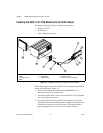
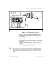
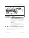
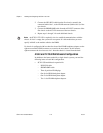
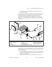
2. Connect the HV8-HV8 cable from the first chassis, normally the
connector behind slot 1, to the HVAB connector (behind slot 4) of the
next chassis.
3. Connect the SH9MD-9MD cable from the AUX OUT connector of the
first chassis to the AUX IN connector of the next chassis.
4. Repeat steps 1 through 3 for each additional chassis.
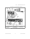
Notes
An SCXI-1127/1128 is required in slot 4 to establish communications with the
chassis. If slot 4 is empty, the system will not operate. It is this module that you must
specify in MAX as the module cabled to the DMM.
If a chassis is configured with less than four slots of the HVAB-backplane adapter, use the
right-most available HVAB connector to extend to the next chassis. In this instance,
right-most means the slot closest to slot 1 when the chassis is viewed from the back.
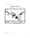
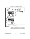
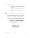
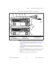
4-Slot and 12-Slot Multichassis Configuration
In addition to the items needed for a single-chassis system, you need the
following items to install this configuration:
• SCXI-1358 multichassis expansion kit
– HV8-HV8 cable
– SH9MD-9MD cable
– Three 8-position HVAB plugs
– One 8-slot HVAB-backplane adapter
– One 2-slot HVAB-backplane adapter
– Two 1-slot HVAB-backplane adapters