


Chapter 2 Using the SCXI-1127/1128
© National Instruments Corporation 2-5 SCXI-1127/1128 User Manual
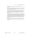
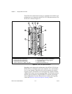
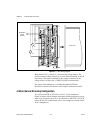
1-Wire Channel Scanning Configuration
The SCXI-1127/1128 has 64, 1-wire channels in the multiplexer mode that
are available through the SCXI-1331 terminal block. Figure 2-4 shows the
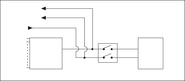
SCXI-1127/1128 configured as a 64-to-1, 1-wire multiplexer. A 1-wire
configuration provides a high channel count because all input signals have
the same reference. This common reference, called 1_WIRE_LO_REF on
the SCXI-1127/1128, is available through the screw terminals on the
SCXI-1331 terminal block.
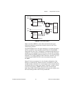
Figure 2-4.
1-Wire Block Diagram
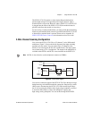
The output of the 64-to-1 multiplexer is available through the OUT0+ and
OUT0– screw terminals on the SCXI-1331. You can also connect the output
of the SCXI-1127/1128 to the HVAB backplane using switch AB0 to make
the connection.
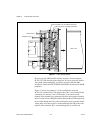
On power up, switch AB0 is open, disconnecting the SCXI-1127/1128
from the high-voltage bus. If you are using the module with a high-voltage
backplane, you need to close the AB0 switch to connect the multiplexer
output to the HVAB backplane. You can do this through NI-SWITCH.
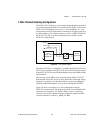
Figure 2-5 shows an example of a 1-wire configuration using the
SCXI-1331 terminal block. The diagram shows the 1-wire terminal block
connections for channels 4, 24, and 59. Channel 4 (R
1
) is measuring a
resistance. The positive channel is labeled 4 while the negative terminal
(common reference) is labeled 1_WIRE_LO_REF.
HVAB
Backplane
64-to-1
Single-ended
Multiplexer
AB0
Switch
Out0+
1_WIRE_LO_REF
Out0–
0
1
63