


Chapter 2 Using the SCXI-1127/1128
SCXI-1127/1128 User Manual 2-8 ni.com
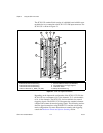
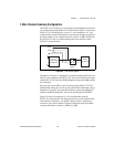
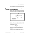
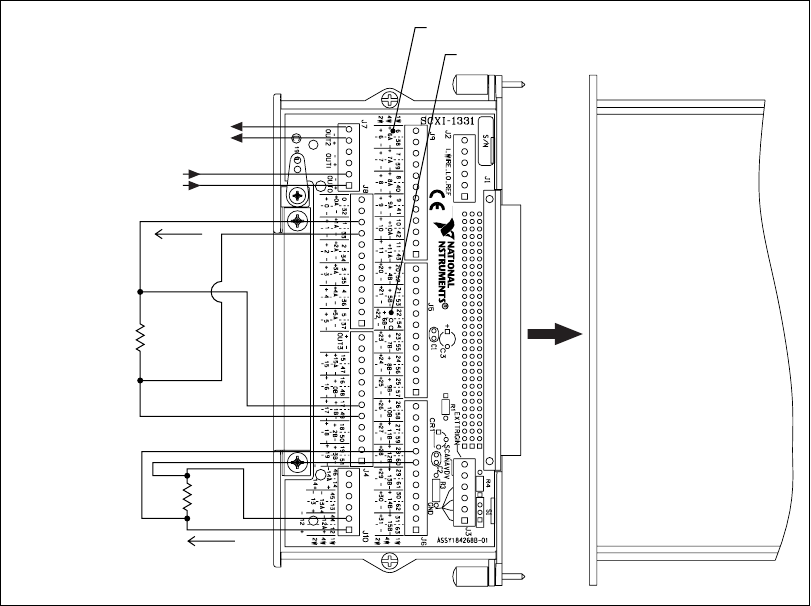
Figure 2-7. 4-Wire Wiring Diagram
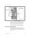
On power up, the AB0 and AB2 switches are open, disconnecting the
SCXI-1127/1128 from the high-voltage bus. If you are using this module
with a high-voltage backplane, you need to close the AB0 and AB2
switches to connect the EXCITATION and SENSE commons to the HVAB
backplane.
Figure 2-7 shows an example of a 4-wire configuration using the
SCXI-1331 terminal block. The diagram shows the 4-wire terminal block
connections for channels 1 and 12. Resistance is measured on both
channels. Each channel has excitation pair positive and negative terminals
labeled 1A and 12A and SENSE terminals labeled 1B and 12B respectively.
R1 is excited through the 12A positive and negative screw terminals and the
voltage drop across the resistor is measured through the 12B positive and
negative screw terminals. R2 is excited through the 1A positive and
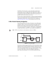
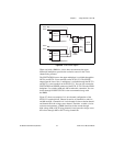
SCXI-1127
R
2
–
–
+
+
R
2
Sense Output
6A ± Excitation for Four-Wire Channel 6
6B ± Sense for Four-Wire Channel 6
–
+
–
+
Excitation Input
Iex
Iex
I