


Chapter 2 Using the SCXI-1127/1128
SCXI-1127/1128 User Manual 2-6 ni.com
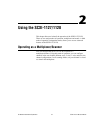
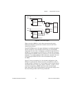
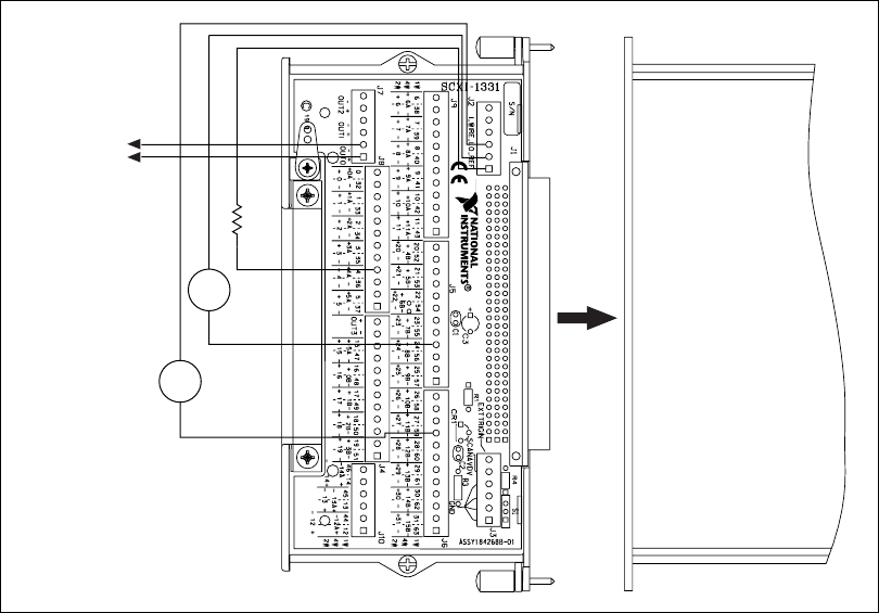
Figure 2-5. 1-Wire Wiring Diagram
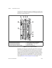
Both channel 24 (V
1
) and 59 (V
2
) are measuring voltage sources. The
positive terminal of these sources go to screw terminals labeled 24 and 59
respectively. The negative terminals or the common reference for the
voltage source is wired to the 1_WIRE_LO_REF screw terminals.
The output of the multiplexer is available through the OUT0 bus.
Resistance is measured at channel 4 and voltage at channels 24 and 59.
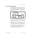
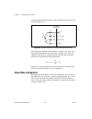
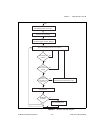
4-Wire Channel Scanning Configuration
You can use an SCXI-1127/1128 as a 16-to-1, 4-wire multiplexer.
Figure 2-6 shows a block diagram of the input switching structure in 4-wire
mode. You can connect up to 16, 4-wire channels to the SCXI-1127/1128
using a SCXI-1331 terminal block. The 4-wire multiplexer consists of dual
16-to-1 multiplexers.
SCXI-1127
R
1
V
1
Multiplexer
Output
OUT0±
V
2
–
–
+
+
–
+