


Appendix D SCXI-1127/1128 Front Connector
SCXI-1127/1128 User Manual D-6 ni.com
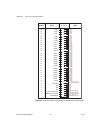
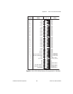
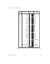
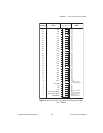
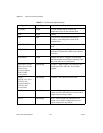
Table D-1. Front Connector Signal Description
Signal Name Type Description
+5 V(ISO) Output +5 VDC isolated source—Powers the
temperature sensor on the terminal block
GND Output Ground
CJS± Input Cold-junction Temperature Sensor Input—
Connects to the temperature sensor of the
terminal block
1_WIRE_LO_REF Input The common reference signal used in one-wire
mode
EXT_TRIG_IN Input External Trigger Input—Trigger from an
instrument to advance the switch card to the next
scan entry
SCANADVD Output Scanner Advanced—Trigger to an instrument
that indicated the switch card has advanced to the
next scan and relays are debounced
CH<0..63>± (1-wire)
CH<0..31> ±(2-wire)
CH<0..15>A±
(4-wire excitation)
CH<0..15>Β±
(4-wire sense)
Input/Output Channels—Where signals are connected to the
switch card. CHx+ and CHx– are switched
together
OUT0±
OUT<0..3> (2-wire)
OUT<0..1>A±
(4-wire excitation)
OUT<0..1>Β±
(4-wire sense)
Input/Output Common—The common for each bank
C<0..7> Input/Output Columns—Where signal are connected to the
switch card. The card behaves as a matrix when
proper external wiring is added
R<0..3> Input/Output Rows—Where signals are connected to the
switch card. In matrix configuration any row
can be connected to any column