


1. Overview
3
1.2 System and Partial Failure Analysis Overview
1.2.1 Failure Analysis for IP8800/S6700, IP8800/S6600, and IP8800/
S6300
If a failure occurs during operation and the system can be visually and directly checked, follow the procedure in
"2.1 Troubleshooting for IP8800/S6700, IP8800/S6600, and IP8800/S6300" to troubleshoot.
The device status is displayed on the basic control unit (BCU) for IP8800/S6700, the control and switching unit (CSU)
for IP8800/S6600, and management and switching unit (MSU) for IP8800/S6300. LED display of BCS/CSU/MSU is
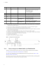
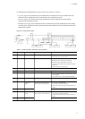
shown in the "Table 1-1: LED Indications, Switches, and Connectors." Also, Front panel layout is shown in the "Figure
1-1: Example of Front Panel Layout."
For LEDs of optional components other than BCU/CSU/MSU shown as an example (BSU, NIF, power supply, and fan
unit) and the layout of front panel other than "Figure 1-1: Example of Front Panel Layout," see the manual "Hardware
Installation Guide."
Even though the system cannot be visually and directly checked, troubleshooting can be performed similarly by
checking system LEDs using the operation command from the remote operation terminal.
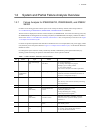
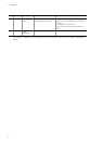
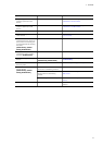
Table 1-1: LED Indications, Switches, and Connectors
No. Name Type Status Description
1STATUS
LED: Green/Orange/
Red
Operation status of BCU/
CSU/MSU
Lit in green: Operational
Lit in orange: Self-diagnosis in progress
Blinking in green: Loading software
Lit in red: Failure detected
OFF: Power is OFF (BCU/CSU/MSU replaceable)
*1
2SYSTEM
OPERATION
PANEL
LCD and operation key System operation panel
Displays the device information, operation
instructions, and failure information (for details, see
the manual "Configuration Settings")
3 ACC LED: Green Memory card status
Lit in green: Accessing the memory card (never detach
it).
OFF: Memory card in idle state (memory card setting/
removal permitted)
4 SD CARD Connector SD card slot SD card slot
5RESET
Switch
(Non-locked)
System manual reset
switch
Pressing and holding for a second
: When the system fails
*2*3
Pressing and holding for 5 seconds
: When the password is forgotten
*2*4
6ACH
Switch
(Non-locked)
BCU/CSU/MSU
switchover switch
When BCU/CSU/MSU is redundant, switchover
between the active system and standby system is
performed
.
*2*5
7 ACTIVE LED: Green BCU/CSU/MSU operation
status
Lit in green: Active system
OFF: Standby system
8SYSTEM1
LED: Green/Orange/
Red
System status
Lit in green: Operational
Lit in orange: System partial failure detected
Lit in red: System failure detected