


ISDN Features
Primary Rate Interface (PRI), Placing Calls
Aspire ISDN PRI Manual ◆ 29
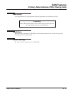
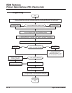
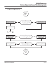
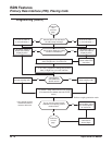
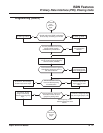
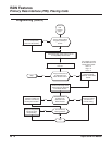
Programming (Cont’d)
➻
10-03-01 : PCB Setup - ISDN Line Mode
Setup and confirm the Basic Configuration data for each PCB. This program selects the ISDN Line
Mode: 0=Not set, 1=T-Bus, 2=S-Bus, 3=Network Mode (Leased Line), 4=Network Mode (Intercon-
nected Line), 5=Network Mode (Interconnected Line, Fixed Layer 1=NT), 6=S-Point (Leased Line).
The option selected here determines the clock source for a networked system. With option 3, telco
sends the clock to the master and slave systems. With option 4, the master system sends the clock to
telco which then sends the clock to the slave system (with no telco, the master system sends the clock
directly to the slave system). With option 5, the master and slave systems both send the clock to telco.
➻ 10-03-02 : PCB Setup - Logical Port Number
Setup and confirm the Basic Configuration data for each PCB. This program displays the start port
number of a PRI line. Thirty logic ports are automatically assigned to a PRI line (T-Bus = 1-200, S-Bus
= 1-256).
➻ 10-03-03 : PCB Setup - CRC Multi-Frame (CRC4)
Setup and confirm the Basic Configuration data for each PCB. This program determines whether or not
the CRC Multi-Frame (CRC4) is used (0=off, 1=on).
➻ 10-03-04 : PCB Setup - Layer 3 Timer Type
Setup and confirm the Basic Configuration data for each PCB. This program selects the Layer 3 timer
type (1-5). Each timer value of Layer 3 is set up for each type in Program 81-06 (T-Bus) and Program
82-06 (S-Bus).
➻ 10-03-05 : PCB Setup - CLIP Information
Based on this setting, the system will include a “Presentation Allowed” (1) or “Presentation Restricted”
(0) in the Setup message to allow or deny the Calling Party Number. Program 15-01-04 must also be
set to a ‘1’ if this option is enabled.
➻ 10-03-06 : PCB Setup - Length of Cable
Setup and confirm the Basic Configuration data for each PCB. Select the length of cable to be used
(0=0-40m, 1=40 81m, 2=81-122m, 3=122-162m, 4=162-200m).
➻ 10-03-07 : PCB Setup - S-Point DID Digits
Setup and confirm the Basic Configuration data for each PCB. This program selects number of DID
digits to be received (0-4).
➻ 10-03-08 : PCB Setup - Dial Sending Mode
Setup and confirm the Basic Configuration data for each PCB. Select either enblock or overlap sending
(0=Enblock Sending, 1=Overlap Sending).
➻ 10-03-09 : PCB Setup - Dial Information Element
Setup and confirm the Basic Configuration data for each PCB. If Overlap Sending is selected in Pro-
gram 10-03-08, select either Keypad Facility (0) or Called Party Number (1) for the dial information
element.
➻ 10-03-10 : PCB Setup - Master/Slave System
Setup and confirm the Basic Configuration data for each PCB. If the system is networked, set the sys-
tem as either the slave (0) or master (1) system.
➻ 10-03-11 : PCB Setup - Networking System Number
Setup and confirm the Basic Configuration data for each PCB. If the system is networked, define the
system number (0-50).
➻ 10-03-12 : PCB Setup - Short/Long Haul
Setup and confirm the Basic Configuration data for each PCB. Select either short-haul (0) or long-haul
(1).