


sDIO Module Connectors and Indicators
Adept SmartController User’s Guide, Rev. E 103
Configuring a System with an sDIO and a RIO
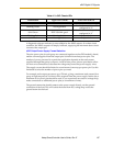
When a system contains an sDIO module and a RIO, you must use the DC_SETUP.V2
program to select a block number for the RIO. This is described in the documentation
supplied with the RIO. Typically, you would use default block 16 for the sDIO, and select
block 17 for the RIO.
Once the RIO block number is selected, then you assign I/O signal numbers for the RIO
using the CONFIG_C.V2 utility. This is the same process as described earlier for the sDIO.
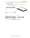
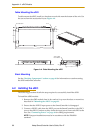
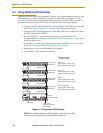
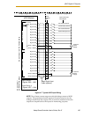
A.5 sDIO Module Connectors and Indicators
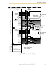
Figure A-6. sDIO
1. Status LEDs.
Two
LEDs indicate link status of the IEEE 1394 connection and system status.
LINK: Green LED = communication with another device over IEEE 1394
connection OK.
OK/SF: Red LED = output driver fault detected due to excessive temperature or
current (output is automatically shut down), solid green LED = communication
with controller OK, blinking green = not configured in software.
2. IEEE 1394 ports: Connects to one of the SmartServo ports on SmartController or
IEEE 1394 ports on additional sDIO units.
3. X1 Output: 44-pin female D-sub connector, for digital output signals 0033-0048.
4. X2 Output: 44-pin female D-sub connector, for digital output signals 0049-0064.
5. X3 Input: 26-pin female D-sub connector, for digital input signals 1033-1048.
6. X4 Input: 26-pin female D-sub connector, for digital input signals 1049-1064.
NOTE: For installations that use two or more sDIO modules, the above
signal numbers apply to the signals for the first sDIO. See the V
+
documentation for information on configuring two or more sDIO
modules.
7. Two 24VDC connectors: Connect power from the XDC2 connector on the
SmartController to the XDC1 connector on the sDIO (see the “Connecting Power”
section on page 30 for power specifications).
SF
IEEE-1394
X2
SC-DIO
LINK
*S/N 3563-XXXXX*
X1
24V 0.5A
R
OK
X4
- + - +
1.1 1.2
XDC1 XDC2
X3
1
2
3
7
4 5 6