


Camera Cable Pin and Signal Information
Adept SmartController User’s Guide, Rev. E 77
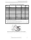
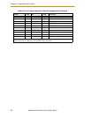
Figure 4-4. Pin Locations for Camera Cable Connector (12-Pin Hirose Male)
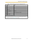
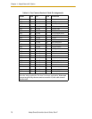
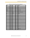
Table 4-3. Adept 10-Meter Camera Cable Pin Assignments
Pin # at
controller
end (male) Function Notes
Wire Color
(typical)
Pin # at
camera end,
(female)
1 Power return gray 1
2 +12V power to camera yellow 2
3 Shield (video) red-shield 3
4 Video from camera red-signal 4
5
Shield (Hd) orange-
shield
5
6
Hd (horizontal drive) to camera orange-
signal
6
7 Vd (vertical drive) to camera black-signal 7
8
Shield (Clock) from camera (cam. 1
& 2 only)
white-shield
8
9
Pixel clock from camera (cam. 1
& 2 only)
white-signal
9
10 not used reserved brown 10
11 not used reserved blue 11
12 Shield (Vd) black-shield 12
• Connector at controller end: 12-Pin Hirose Male, HR10A-10P-12P, with ground terminal lug
(shield). See Figure 4-4 for pin locations.
• Connector at camera end: 12-Pin Hirose Female, HR10A-10P-12S.
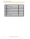
• Cable specifications: 12 conductors, including 4 coax pairs, 4 discrete conductors, and overall
shield. At each end the shield is clamped to connector body.
9
10
12
11
8
7
6
5
4
3
2
1
Black
Brown
Gray
Blue
Yellow
White
Orange
Red
Overall
Braided Shield
Wire colors
may vary