


sDIO Digital I/O Signals
Adept SmartController User’s Guide, Rev. E 107
A diagnostic software indicator is not available for the XDIO outputs. In a short circuit
condition, the XDIO outputs will simply fold back, supplying the maximum short circuit
current to the output pin.
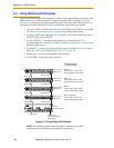
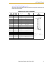
sDIO Output Power Supply Current Selection
The nine power pins for each group are connected together on the sDIO module’s board,
and the current supplied from the output pins is drawn from these power pins. The
number of power pins used in a particular application depends on the total current
supplied through that group’s outputs. A total of nine power pins are provided to allow
for more wire connections to decrease the voltage drop across the power supply wires.
The supply current should be limited to a maximum of one amp per power pin. Use this
limitation to select the number of power pins you need.
For example, each output can source up to 700 mA, giving a maximum total current (for a
group of eight outputs) of 5.6A that will be required from the power supply. In this case, a
minimum of six power pins should be used. If you experience an excessive voltage drop,
make connections to additional power pins (to a maximum of nine).
The ground connection should connect to the power supply directly, not the ground
connection of the load. This will isolate the board from any voltage drop across the
ground return for the load.
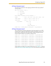
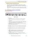
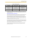
Table A-3. sDIO Chassis LEDs
Illumination Upper LED (LINK) Lower LED (OK SF)
None No IEEE 1394 link Local software not running
Blinking Green Not Applicable
Local software active, not
configured in V
+
Solid Green IEEE 1394 link good
Local software active, and
configured in V
+
Blinking Red Not Applicable Output fault
Solid Red Not Applicable Output fault