


Connecting Customer-Supplied Safety and Power Control Equipment
Adept SmartController User’s Guide, Rev. E 55
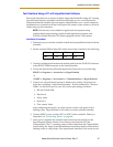
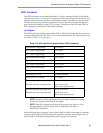
User E-Stop Indication - Remote Sensing of E-Stop
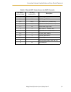
Two pairs of pins on the XUSR connector (pins 7, 20 and 8, 21) provide voltage-free
contacts, one for each channel, to indicate whether the E-Stop chain, as described above,
on that channel is closed. Both switches are closed on each of the redundant circuits in
normal condition (no E-Stop). The user may use these contacts to generate an E-Stop for
other equipment in the workcell. This output does NOT report status of “line E-Stop”
input (see the section below for more information). The load on the contacts must not
exceed 40VDC or 30VAC at a maximum of 1A.
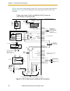
These voltage-free contacts are provided by a redundant, cyclically checked,
positive-drive, safety relay circuit for EN-954-1 Category 3 operation (see Figure 3-5 on
page 53 and Table 3-7 on page 49 for the customer E-Stop circuitry).
Line E-Stop Input
The XUSR connector on the SmartController contains a two-channel Line E-Stop input for
workcell or other equipment emergency stop inputs. Generally, the customer E-Stop
Indication contact outputs are used to cause an emergency stop in such external
equipment. Thus, if one were to wire the same equipment’s outputs into the customer
E-Stop input (that is, in series with the local robot’s E-Stop push buttons), a lock up
situation can occur.
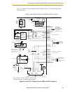
The Line E-Stop input comes into the circuit at a point where it cannot affect the customer
E-Stop indication relays and will not cause such a lock up situation. For any situation
where two systems should be “cross-coupled”, for example, the customer E-Stop
indication of one SmartController is to be connected to the input of another
SmartController, the Line E-Stop input is the point to bring in the other SmartController’s
output contacts, see Figure 3-5 on page 53 for more information.
Do not use the Line E-Stop for such devices as local E-Stop push buttons since their status
should be reported to the outside on the local customer E-Stop indication output contact
while the Line E-Stop inputs will not.
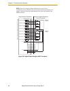
Muted Safety Gate E-Stop Circuitry
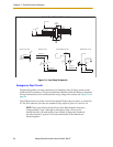
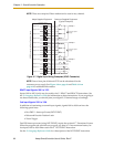
Two pairs of pins on the XUSR connector (pins 5, 18 and 6, 19) provide connections for a
safety gate designed to yield an E-Stop allowing access to the workspace of the robot in
Manual mode only, not in Automatic mode. The E-Stop is said to be “muted” in Manual
mode (see Figure 3-5 on page 53, Table 3-7 on page 49, Table 3-8 on page 50, and
Table 3-9 on page 51 for the customer E-Stop circuitry).
The muted capability is useful for the situation where a shutdown must occur if the cell
gate is opened in normal production mode, but you need to open the gate in manual
mode. In muted mode, the gate can be left open for personnel to work in the robot cell.
However, safety is maintained because of the speed restriction.
CAUTION: If the cell gate must always cause a robot
shutdown, do not wire the gate switch into the muted
safety gate inputs. Instead, wire the gate switch contacts in
series with the user E-Stop inputs.