


Chapter 3 - SmartController Operation
40 Adept SmartController User’s Guide, Rev. E
13. 24VDC connectors
Connect power from a customer-supplied 24VDC power supply to the XDC1 connector (see
the “Connecting Power” section on page 30 for information); if using an sDIO or an sMI6,
connect a separate cable from the XDC2 connector on the SmartController to the XDC1
connector on the sDIO or sMI6.
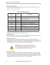
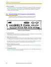
3.2 SmartController CX Connectors and Indicators
The SmartController CX has all the of connectors and indicators from the
SmartController CS, plus the additional ones described in this section.
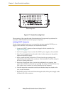
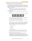
Figure 3-2. SmartController CX
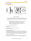
1. Camera connector
This connector is present when the AdeptVision sAVI option is installed. The camera breakout
cables connect here. See Chapter 4 for complete information.
2. IEEE-1394 ports 2.1 and 2.2
These ports connect the Adept SmartController with an IEEE-1394 port on a Windows-based
PC. This provides a connection for Adept's ActiveVR Interface software, available in V
+
16.0.
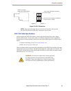
Do not use ports 2.1 or 2.2 to connect Adept Smart Servo-compatible products, or to connect
non-Adept-qualified peripherals, such as cameras, hard drives, printers, etc.
3. RS-232-1 and RS-232-2 connector
These are additional RS-232 serial ports for general use. See Section 3.5 on page 44 for more
information.
4. Belt Encoder connector
A 15-pin D-Sub connector for up to two belt encoders in a conveyor tracking installation. See
Section 3.9 on page 65 for more information.
R
ON
SmartServo IEEE-1394
1 2 3 4
SF ES HD
SW1
1.1 1.2 2.1 2.2
OK
123
XDIO
LANHPE
OFF
XSYS
CAMERA
Eth 10/100
XUSR
Device Net
XFP
RS-232/TERM
RS-232-1
XMCP
BELT ENCODER
SmartController CX
-+ -+
RS-422/485
XDC1 XDC2
24V 5A
*S/N 3562-XXXXX*
RS-232-2