


Chapter 3 - SmartController Operation
38 Adept SmartController User’s Guide, Rev. E
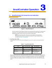
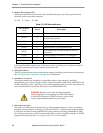
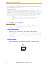
2. Bottom Three Status LEDs
The bottom three LEDs on the front of the SmartController give the following information
about the status of the main controller.
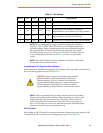
O = Off G = Green R = Red
If the SmartController displays any of the above errors, cycle the power off, then on again. If
the problem persists, then contact Adept Customer Service.
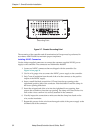
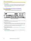
3. SW1 DIP switches
The DIP switches define certain configuration settings (including auto boot and user interface).
See “Configuring the Controller” on page 42 for information.
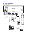
4. SmartServo 1.1 and 1.2
These ports connect any SmartServo-compatible product to the controller; including
SmartModules, Servo Kits, AdeptSix robots, Adept Cobra s600 or s800 robots, sMI6, sDIO, and
FireBlox amplifiers. The 1.1 and 1.2 ports are interchangeable, either one can be used. (Note: on
early SmartController CS models, these ports were labeled IEEE-1394.)
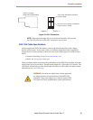
5. DeviceNet connector
DeviceNet is a field bus for industrial devices. This standard supports a variety of products,
including sensors, digital I/O, analog I/O, RS-232, and PLCs. Adept directly supports digital
I/O devices and has currently qualified DeviceNet products from Wago and Beckhoff. Other
DeviceNet product types, such as keypads and displays, can be controlled using the V
+
FCMD
program instruction (see the V+ Language Reference Guide for details).
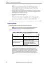
Table 3-2. LED Status Indicators
LED Display
1 2 3
Error # Description
O-O-O 0 No error.
R-O-O 1
System clock is dead or too fast. Clock interrupts
are not being received.
O-R-O 2 Hardware configuration error.
O-O-R 4 Memory test failure. Free storage error.
O-R-R 6 Software serial I/O configuration error.
R-R-R 7
Initial display set by hardware before software
has started.
G-O-O 9 Transient display set when PCI is configured.
O-O-G C Uninitialized trap.
G-O-G D Bus error detected.
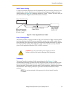
WARNING: Remove power from the SmartController
before plugging in or unplugging any IEEE-1394 cables to
or from these connectors. Failure to remove power could
result in unpredictable behavior by the system.